LIGHTING SYSTEM DETAILS
-
FUNCTION OF MAIN COMPONENTS
-
Daytime Running Light System (Models with Daytime Running Light System)
Component Function Headlight Assembly Daytime Running Lights The Light Emitting Diode (LED) light illuminates. Main Body ECU (Multiplex Network Body ECU) The main body ECU (multiplex network body ECU) receives various signals and illuminates the Daytime Running Lights by the integration relay (DRL relay). Headlight Dimmer Switch Assembly Light Control Switch The light control switch outputs a light control signal and transmits it to the main body ECU (multiplex network body ECU). -
High Intensity Discharge (HID) Headlight System
Component Function Headlight Dimmer Switch Assembly The headlight dimmer switch assembly transmits a HEAD position signal to the main body ECU (multiplex network body ECU). Main Body ECU (Multiplex Network Body ECU) The main body ECU (multiplex network body ECU) receives the HEAD position signal and transmits a signal to the light control ECU. Headlight Assembly Discharge Bulb The discharge bulb light illuminates ahead over a broader area and further forward, increasing the area visible to the driver. Light Control ECU The light control ECU transforms battery voltage to a high voltage of up to 30000 V and applies it to the discharge bulbs in order to illuminate them. Combination Meter Assembly Taillight Indicator Light The taillight indicator lights up to inform the driver when the taillights turn on. Master Warning Light The master warning light illuminates to inform the driver when the High Intensity Discharge (HID) Headlight System detects malfunctions in this system. Multi-information Display The multi-information display displays a warning message to inform the driver when the High Intensity Discharge (HID) Headlight System detects a malfunction in this system. Headlight Relay The relay supplies the power to the light control ECU. -
Intelligent Adaptive Front-lighting System (AFS)
Component Function Headlight Swivel ECU Assembly
-
The headlight swivel ECU assembly receives various signals, calculates the target lighting angle, and actuates the headlight swivel motor.
-
When the headlight swivel ECU assembly detects malfunctions, the headlight swivel ECU assembly flashes the AFS OFF indicator light.
-
This ECU provides initial set control and a fail-safe function.
Headlight Assemblies (LH, RH) Headlight Swivel Motors (LH, RH) Driven by the headlight swivel ECU assembly and the headlight swivel motor moves the low beam left or right to the angle calculated by the headlight swivel ECU assembly. Steering Sensor The steering sensor outputs the steering angle. Main Body ECU (Multiplex Network Body ECU) The main body ECU (multiplex network body ECU) receives a head position signal from the light control switch and transmits it to the headlight swivel ECU assembly. Skid Control ECU Assembly
-
The skid control ECU assembly transmits the signals of the front RH and LH speed sensors to the headlight swivel ECU assembly.
-
The skid control ECU assembly receives the zero point signal from the steering sensor and transmits it to the headlight swivel ECU assembly.
Headlight Dimmer Switch Assembly Light Control Switch The light control switch transmits a HEAD position signal to the main body ECU (multiplex network body ECU). Combination Meter Assembly AFS OFF Indicator Light
-
The AFS OFF indicator light lights up when the AFS control is stopped by the headlight swivel main switch.
-
The AFS OFF indicator light flashes when the headlight swivel ECU assembly detects a malfunction.
Multi-information Display The multi-information display displays a warning message to inform the driver when the headlight swivel assembly detects a malfunction in this system. Headlight Swivel Main Switch The headlight swivel main switch outputs an AFS OFF signal and transmits it to the headlight swivel ECU assembly. -
-
Automatic High Beam System
Component Function Headlight Swivel ECU Assembly
-
The headlight swivel ECU assembly receives high beam actuation signals from the automatic high beam sensor using LIN communication (for automatic high beam actuation).
-
The headlight swivel ECU assembly acts as the gateway between the automatic high beam sensor and CAN (V bus).
-
The headlight swivel ECU assembly sends high beam actuation signals to the main body ECU (multiplex network body ECU) via CAN communication.
Inner Rear View Mirror Automatic High Beam Sensor The automatic high beam sensor determines when to turn the high beams on and off after identifying the lights of oncoming vehicles, preceding vehicles and other lights from the picture information of its camera sensor. Then, the sensor sends high beam request signals to the headlight swivel ECU assembly using LIN communication. ECM The ECM receives the shift position signals from the park/neutral position switch assembly and transmits a signal to the headlight swivel ECU assembly. Main Body ECU (Multiplex Network Body ECU)
-
The main body ECU (multiplex network body ECU) receives an AUTO on signal and high beam position signal from the headlight dimmer switch assembly.
-
The main body ECU (multiplex network body ECU) receives high beam request signals from the headlight swivel ECU assembly and transmits a signal to the head light assembly (headlight solenoid).
Headlight Solenoid The headlight solenoid rotates the shade, which is built into headlight assembly, down to allow use of the lower illumination area, thus increasing the illumination area when the high beam request signal is received. Skid Control ECU The skid control ECU outputs information about the speed of the wheel. This information is used by the automatic high beam control to control switching between the high beams and low beams of the automatic high beam system. Park/Neutral Position Switch Assembly The park/neutral start switch assembly outputs signals to indicate the position of the shift lever. Based on these signals, the ECM determines the intended shift condition and direction of vehicle movement. The direction of vehicle movement is used by the automatic high beam sensor for automatic high beam control. Headlight Dimmer Switch Assembly Light Control Switch The light control switch transmits an AUTO position signal to the main body ECU (multiplex network body ECU). Dimmer Switch The dimmer switch transmits high beam position signal to the main body ECU (multiplex network body ECU). Integration Control and Panel Assembly Automatic High Beam Switch The automatic high beam switch outputs the automatic high beam system on or off signal to the main body ECU (multiplex network body ECU). Automatic Light Control Sensor The automatic light control sensor detects the ambient light level and transmits a signal to the main body ECU (multiplex network body ECU). Yawrate Sensor The yawrate sensor outputs the yaw rate information. Combination Meter Assembly Automatic High Beam Indicator Light
-
The automatic high beam indicator light illuminates to inform the driver when the automatic high beam system is activated.
-
The automatic high beam indicator light flashes to inform the driver when malfunctions are detected in this system.
High Beam Indicator Light The high beam indicator light illuminates to inform the driver when the high beams are on. Multi-information Display When the headlight dimmer switch is not in high beam position and the automatic high beam switch is on, then the multi-information display shows an advice message. -
-
Automatic Headlight Beam Level Control System
Component Function Headlight Swivel ECU Assembly
-
The headlight swivel ECU detects changes of vehicle movement based on the rear height control sensor sub-assembly LH and front speed sensor.
-
The headlight swivel ECU assembly outputs control signals to the headlight swivel motors based on the detected value.
-
This ECU provides initial set control and a fail-safe function.
Headlight Assemblies (LH, RH) Headlight Swivel Motors (LH, RH) Based on the signals received from the headlight swivel ECU assembly, each headlight swivel motor moves the projector unit in the headlight to vary its angle. Main Body ECU (Multiplex Network Body ECU) The main body ECU (multiplex network body ECU) receives a head position signal from the light control switch and transmits it to the headlight swivel ECU assembly. Skid Control ECU Assembly The skid control ECU assembly outputs information about the speed of the front wheels. This information is used by the automatic headlight beam level control. Headlight Dimmer Switch Assembly Light Control Switch The light control switch transmits a HEAD position signal to the main body ECU (multiplex network body ECU). Rear Height Control Sensor Sub-assembly Rear LH The rear height control sensor sub-assembly LH detects vehicle movement and transmits a signal to the headlight swivel ECU assembly. Combination Meter Assembly AFS OFF Indicator Light The AFS OFF indicator light flashes to inform the driver when the headlight swivel ECU assembly detects malfunctions in this system. -
-
Automatic Light Control System
Component Function Headlight Relay The headlight relay supplies power to the light control ECU. Integration Relay (TAIL Relay) The TAIL relay supplies power to the taillights, clearance lights, side marker lights and license plate lights. Certification ECU (Smart Key ECU Assembly) The certification ECU (smart key ECU assembly) receives the engine switch push signal and transmits it to the main body ECU (multiplex network body ECU). Main Body ECU (Multiplex Network Body ECU) The main body ECU (multiplex network body ECU) receives various signals and illuminates the headlights, taillights, clearance lights, side marker lights and license plate lights. Automatic Light Control Sensor The automatic light control sensor detects the ambient light level. Headlight Dimmer Switch Assembly Light Control Switch The light control switch transmits an AUTO position signal to the main body ECU (multiplex network body ECU). Combination Meter Assembly Taillight Indicator Light The taillight indicator lights up to inform the driver when the taillights turn on. -
Light Auto Turn-off System
Component Function Headlight Relay The headlight relays shut down the power to the head lights. Integration Relay (TAIL Relay) The TAIL relay shuts down the power to the taillights, clearance lights, side marker lights and license plate lights. Main Body ECU (Multiplex Network Body ECU) The main body ECU (multiplex network body ECU) receives various signals, and turns off the exterior lights. Headlight Dimmer Switch Assembly Light Control Switch The light control switch transmits a light control position signal to the main body ECU (multiplex network body ECU). Courtesy Light Switch Assemblies Front (LH, RH), Rear (LH, RH) The courtesy light switch assembly detects whether a door is open or closed and transmits a signal to the main body ECU (multiplex network body ECU). Door Unlock Detection Switches Front (LH, RH), Rear (LH, RH) The door unlock detection switch detects the whether a door is locked or unlocked and transmits a signal to the main body ECU (multiplex network body ECU). Door Control Receiver The door control receiver receives the ID code from the electrical ley transmitter subassembly in the actuation area and transmits it to the main body ECU (multiplex network body ECU). Certification ECU (Smart Key ECU Assembly)
-
The certification ECU (smart key ECU assembly) judges and certifies the ID code from the door control receiver.
-
The certification ECU (smart key ECU assembly) receives the engine switch push signal and transmits it to the main body ECU (multiplex network body ECU).
-
-
Door Mirror Foot Light System
Component Function Door Lock Control Switch Driver, Front Passenger The door lock control switch outputs the lock/unlock signal to the main body ECU (multiplex network body ECU) or power window master switch. Certification ECU (Smart Key ECU Assembly) The certification ECU (smart key ECU assembly) judges and certifies the ID code. Main Body ECU (Multiplex Network Body ECU) The main body ECU (multiplex network body ECU) receives various signals and transmits them to the multiplex network door ECUs. Multiplex Network Door ECUs (LH, RH) The multiplex network door ECUs receive various signals and illuminates the door mirror foot lights. ECM The ECM receives the shift position signals from the park/neutral position switch assembly and transmits them to the main body ECU (multiplex network body ECU). Courtesy Light Switch Assemblies Front (LH, RH), Rear (LH, RH) The courtesy light switch assembly detects whether a door is open or closed and transmits a signal to the main body ECU (multiplex network body ECU). Door Unlock Detection Switches Front (LH, RH), Rear (LH, RH) The door unlock detection switch detects the whether a door is locked or unlocked and transmits a signal to the main body ECU (multiplex network body ECU). Multiplex Network Master Switch Assembly The multiplex network master switch assembly sends the driver side door lock switch signal to the main body ECU (multiplex network body ECU). -
Illumination System
Component Function Certification ECU (Smart Key ECU Assembly) The certification ECU (smart key ECU assembly) judges and certifies the ID code from the door control receiver. Main Body ECU (Multiplex Network Body ECU) The main body ECU (multiplex network body ECU) receives various signals and illuminates the clearance lights, taillights and license plate lights. Door Control Receiver The door control receiver receives the ID code from the electrical ley transmitter subassembly in the actuation area and transmits it to the main body ECU (multiplex network body ECU). Headlight Assemblies (LH, RH) Clearance Lights The Light Emitting Diode (LED) light illuminates. Rear Combination Light Assemblies (LH, RH) Taillights The Light Emitting Diode (LED) light illuminates. Rear Light Assemblies (LH, RH) Automatic Light Control Sensor Assembly The automatic light control sensor assembly detects the ambient light level and transmits them to the main body ECU (multiplex network body ECU).
-
-
OPERATING CONDITION
-
Daytime Running Light System (Models with Daytime Running Light System)
-
The daytime running lights illuminate when the following conditions are met:
-
An engine speed signal is input (engine is running).
-
Light control switch OFF or AUTO position (when taillight is not being controlled by the automatic light control).
-
The parking brake is off.
-
-
-
Intelligent Adaptive Front-lighting System (AFS)
-
The intelligent AFS will operate when all of the following conditions are met:
-
An engine speed signal is input (engine is running).
-
The vehicle is moving forward at a speed above or equal to 10 km/h (6 mph) but below 30 km/h (19 mph).*1
-
The vehicle is moving forward at a speed of 30 km/h (19 mph) or more.*2
-
Steering angle is 27° or more.*1
-
Steering angle is 7.5° or more.*2
-
The headlights are operating in low beam.
-
The AFS is on.
Tech Tips
*1: Low speed control is performed.
*2: Medium-to-high speed control is performed.
-
-
-
Automatic High Beam System
-
The automatic high beam system operates as follows:
Condition Details Active When all of the following conditions are met, the automatic high beam system is activated and the automatic high beam indicator light turns on:
-
The engine switch is on (IG).
-
The headlight dimmer switch assembly is in the AUTO or HEAD position and high beam position.
-
automatic high beam switch is on.
High Beams on When all of the following conditions are met, the automatic high beam system turns on the high beams after a short delay:
-
Vehicle speed is more than approx. 30 km/h (19 mph).
-
The area in front of the vehicle is dark (the automatic light control sensor outputs the night mode signal).
-
No oncoming vehicles are present with the headlights on.
-
No preceding vehicles are present with the taillights on.
-
Few streetlights are present along the street ahead.
High Beams off When any of the following conditions are met, the automatic high beam system turns off the high beams after a short delay:
-
Vehicle speed is less than approx. 30 km/h (19 mph).
-
The area in front of the vehicle is not dark.
-
An oncoming vehicle with headlights on is detected.
-
A preceding vehicle with taillights on is detected.
-
Several streetlights are present along the street ahead.
-
-
-
Light Auto Turn-off System
-
The light auto turn-off system operates as follows:
Condition Details Driver Door-linked When all of the following conditions are met, the exterior lights automatically turn off:
-
The engine switch is turned off or on (ACC).
-
The driver door is closed and then opened.
-
The headlight dimmer switch assembly is in the TAIL position.
Follow Me Home When approx. 30 seconds elapse after all of the following conditions are met, the head lights turn off:
-
The engine switch is turned off.
-
All doors are closed.
-
The headlight dimmer switch assembly is in the pass position, then neutral position.
-
-
-
Door Mirror Foot Light System
-
The door mirror foot light system operates as follows:
Condition Details Actuation Area-linked When all of the following conditions are met, the door mirror lights automatically turn on:
-
The engine switch is off.
-
All doors are closed.
-
The electrical key transmitter sub-assembly is detected in the actuation area.
When the following condition is met, the door mirror lights automatically turn off:
-
The electrical key transmitter sub-assembly is not detected in the actuation area.
Door Unlock-linked When all of the following conditions are met, the door mirror lights automatically turn on:
-
The engine switch is off.
-
Any door is unlocked.
-
All doors are closed.
Door Lock-linked When one of the following conditions is met, the door mirror lights automatically turn off:
-
All doors are locked.
-
All doors are closed.
-
A door lock control switch outputs the lock signal.
Door-linked When the following condition is met, the door mirror lights automatically turn on:
-
The engine switch is off.
-
Any door is opened and then closed.
Delay When approx. 15 seconds elapse after one of the following conditions is met, the door mirror lights turn off:
-
An actuation area-linked function is used.
-
The door unlock-linked function is activated.
-
Any door is opened and then closed.
-
-
-
Emergency Brake Signal
-
The activating and deactivating conditions for the emergency brake signal are as shown in the following table:
Condition Details Emergency Brake Signal Operating Conditions When all of the following conditions are met, the emergency brake signal starts operating:
-
Vehicle speed is above 55 km/h (35 mph).
-
Driver is depressing the brake pedal.
-
Emergency braking is detected from the vehicle deceleration.
Emergency Brake Signal Ending Conditions When any of the following conditions is met, the emergency brake signal stops operating:
-
Driver has released the brake pedal.
-
Emergency braking is no longer detected from the vehicle deceleration.
-
Driver has pressed the hazard warning signal switch.
-
-
-
Illumination System
-
The Illumination system operates as follows:
Condition Details Door Unlock-linked When all of the following conditions are met, the clearance lights and taillights automatically turn on:
-
The engine switch is off.
-
Any door is unlocked.
-
All doors are closed.
Door Lock-linked When one of the following conditions is met, the clearance lights and taillights automatically turn off:
-
All doors are locked.
-
All doors are closed.
-
-
-
-
SYSTEM CONTROL
-
Intelligent AFS (Low Speed Control)
-
The headlight swivel ECU assembly calculates the swivel angle from the steering angle, vehicle speed and drives the headlight swivel motor on the side facing into the turn to illuminate the road ahead during cornering.
Headlight Swivel Motor LH RH Driving Condition (LHD Models) Right Turn 0° Fixed 0° to 10° to Right Left Turn 0° to 20° to Left 0° Fixed Driving Condition (RHD Models) Right Turn 0° Fixed 0° to 20° to Right Left Turn 0° to 10° to Left 0° Fixed
-
-
Intelligent AFS (Medium-to-high Speed Control)
-
Based on the steering angle and vehicle speed, the headlight swivel ECU assembly calculates the swivel angle of the low beam headlights so that the headlights can illuminate the position which the vehicle will reach after 3 seconds, and drives both headlight swivel motors to illuminate the road ahead during cornering.
Headlight Swivel Motor LH RH Driving Condition (LHD Models) Right Turn 0° to 5° to Right 0° to 10° to Right Left Turn 0° to 15° to Left 0° to 7.5° Left Driving Condition (RHD Models) Right Turn 0° to 7.5° to Right 0° to 15° to Right Left Turn 0° to 10° to Left 0° to 5° Left
-
-
Intelligent AFS (Initial Set Control)
-
When the engine is started, the headlight swivel ECU assembly drives the headlight swivel motors, moves the projector headlight to the operation limit in the direction toward the vehicle center and then returns it to the proper position. In this way, the headlight swivel ECU assembly determines the standard position of the headlight.
-
-
-
FUNCTION
-
HID Headlight System
-
The HID headlight system consists of discharge bulbs and light control ECUs.
-
The light control ECU transforms the voltage that is input from the battery to a voltage of up to 30000 V and applies it to the discharge bulbs in order to illuminate them.
-
A fail-safe function is provided as a countermeasure against the high voltage generated when a problem occurs in the headlight system.
-
-
Bi-function
-
When the low beam is selected, the lower illumination area of the discharge bulb is blocked by a shade and only the upper illumination area is used.
-
When the high beam is selected, the headlight solenoid rotates the shade down to allow use of the lower illumination area, thus increasing the illumination area and improving visibility when the high beam is selected.
-
The bi-function is activated by the main body ECU. The main body ECU (multiplex network body ECU) receives a signal to turn on the high beams from the headlight dimmer switch assembly, then activates the built-in headlight solenoid to slide the shade down.
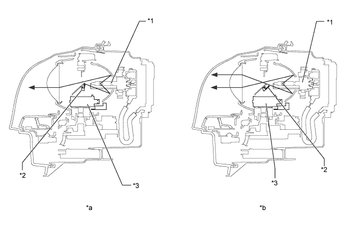
Text in Illustration *1 Discharge Bulb *2 Shade *3 Headlight Solenoid - - *a Low Beam *b High Beam
-
-
Automatic High Beam System
-
When passing an oncoming vehicle:
-
The automatic high beam system turns off the high beams before an oncoming vehicle comes within approximately 800 m (2600 ft.).
-
When an oncoming vehicle passes out of camera sensor range, the automatic high beam system turns the high beams on after a short delay.
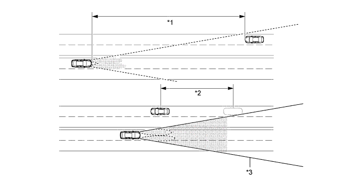
Text in Illustration *1 Approx. 800 m (2600 ft.) *2 Delay *3 Camera Sensor Angle - - Tech Tips
-
The detection distance varies depending on detected objects.
-
The timing of turning on and off the high beams varies depending on the intensity of oncoming (and preceding) vehicle lights.
-
-
When passing a preceding vehicle:
-
When approaching a preceding vehicle, the automatic high beam system turns off the high beams approximately 600 m (1950 ft.) before reaching it.
-
When a preceding vehicle passes out of camera sensor range, the automatic high beam system turns the high beams on after a short delay.
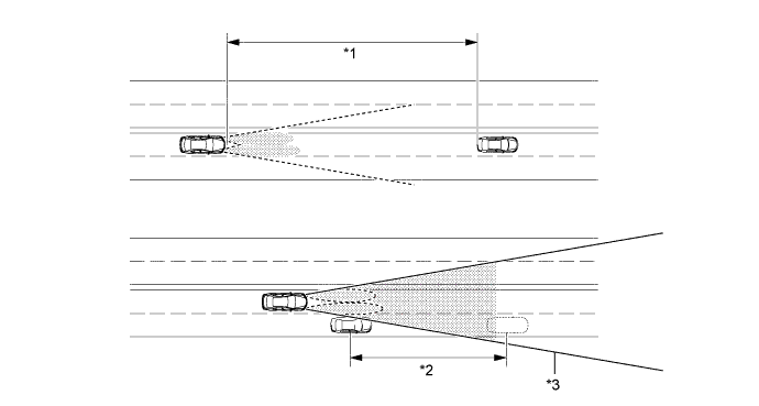
Text in Illustration *1 Approx. 600 m (1950 ft.) *2 Delay *3 Camera Sensor Angle - - Tech Tips
The timing of turning on and off the high beams varies depending on the intensity of the preceding vehicle lights.
-
-
-
Automatic Headlight Beam Level Control System
-
The automatic headlight beam level control system mainly consists of the headlight swivel ECU assembly, rear height control sensor sub-assembly LH and 2 headlight swivel motors. The headlight swivel ECU assembly controls the system.
-
The ECU detects the movement of the suspension from the rear height control sensor subassembly LH and the vehicle speed from the skid control ECU assembly.
-
The ECU then controls the headlight swivel motor based on this information, in order to change the projector headlight unit angle.
-
When the headlight swivel ECU assembly detects that the vehicle is stopped and the engine switch is on (IG), the ECU executes the initial setting of the headlight swivel motors.
-
-
-
CONSTRUCTION
-
HID Headlight Light System
-
Discharge Bulb
-
Instead of the filament contained in an incandescent bulb, a discharge bulb contains an arc tube, which is filled with xenon gas and metal halide.

-
-
-
-
FAIL-SAFE
-
HID Headlight System
-
The light control ECU executes the fail-safe actions listed below in accordance with the problem that has been detected:
Problem Outline Abnormal Input Voltage When the voltage that is input to the light control ECU deviates from the normal operating voltage (10 to 16 V), the light control ECU stops illuminating the headlights. It resumes illuminating the headlights once the voltage reverts to the normal operating voltage. However, if the input voltage decreases after the headlights have illuminated, the headlights will remain illuminated until the input voltage becomes insufficient to light the bulbs. Abnormal Output (Open Circuit or Short Circuit) When an abnormal condition (open or short) occurs in the voltage that is output by the light control ECU, the light control ECU stops illuminating the headlights and will maintain this state until the power is reinstated. Power is reinstated by turning the headlight control switch from off to on. Bulb Open Circuit When a bulb is not inserted in its socket, the light control ECU stops generating high voltage until the bulb is inserted correctly and the power is reinstated. Power is reinstated by turning the headlight control switch from off to on or turning the engine switch from off to on.
-
-
Intelligent AFS and Automatic Headlight Beam Level Control System
-
If the headlight swivel ECU assembly detects a malfunction in the intelligent AFS or automatic headlight beam level control system, it will take the actions indicated in the table below:
Trouble Area System Operation AFS OFF Indicator Light Master Warning Light Intelligent AFS Automatic Headlight Beam Level Control System Headlight Swivel ECU Assembly Control is continued. Control is continued. Flashes Illuminates Speed Sensor Signal
-
If a malfunction occurs only at one of the wheels, it doubles the vehicle speed detection value obtained from the normal wheel.
-
If malfunctions occur at all wheels, continues control only when the vehicle is stopped.
Stops operating after returning to the initial position. Flashes Illuminates Height Control Sensor Sub-assembly Rear LH Stops operating after returning to the initial position.
-
Stops control after returning to initial position (if failure occurs at higher than initial position).
-
Stops control at current condition (if failure occurs at lower than initial position).
Flashes Illuminates Steering Sensor Stops operating after returning to the initial position. Control is continued. Flashes Illuminates Headlight Swivel Motor The normal side swivel actuator comes to the initial position and the abnormal side swivel actuator stops in its current position.
-
Stops control after returning to initial position (if failure occurs at higher than initial position).
-
Stops control at current condition (if failure occurs at lower than initial position).
Flashes Illuminates Communication Signal Stops operating after returning to the initial position. Control is continued. Flashes Illuminates -
-
-