AIR CONDITIONING SYSTEM DETAILS
-
FUNCTION OF MAIN COMPONENTS
-
The air conditioning system consists of the following parts:
Component Function Multi-media Module Receiver Assembly, Multi Display, Remote Touch Allows operation and adjustment of the air conditioning system via switches. Cooler Control Switch Panel* Allows operation and adjustment of the rear air conditioning via switches. Air Conditioning Amplifier Assembly Transmits and receives data to and from the switches and sensors, and controls the air conditioning system. Cooler Compressor Assembly Performs suction, compression and discharge of refrigerant gas. Blower with Fan Motor Sub-assembly A brush less motor is used to achieve a compact and lightweight assembly. Cooler Condenser Assembly A Multi-Flow-IV (MF-IV) sub-cool condenser is used to improve heat exchange efficiency. Heater Radiator Unit Sub-assembly A Straight Flow Aluminum-II (SFA-II) heater radiator is used for compactness and high performance. No. 1 Cooler Evaporator Sub-assembly A Revolutionary super-slim Structure (RS) type cooler evaporator sub-assembly is used for compactness and high performance. No. 1 Cooler Thermistor Detects the temperature of the cool air past the cooler evaporator sub-assembly and transmits the data to the air conditioning amplifier assembly. Thermistor Assembly Detects ambient temperature and outputs it to the air conditioning amplifier assembly. Cooler Thermistor Detects room temperature and outputs it to the air conditioning amplifier assembly. Air Conditioning Thermistor Assembly Detects glass temperature, glass surroundings temperature and glass humidity, and outputs them to the air conditioning amplifier assembly. Automatic Light Control Sensor Detects the changes in the amount of solar energy and outputs them to the air conditioning amplifier assembly. PTC Heater Consists of a Positive Temperature Coefficient (PTC) element, an aluminum fin and a brass plate. Damper Servo Sub-assembly Receives the input of the operation signals from the air conditioning amplifier assembly, operates the motor, and opens and closes the dampers. Air Refiner Element Removes pollen, other particles and smell to provide a comfortable interior space. Air Conditioning Pressure Sensor Detects the refrigerant pressure and sends the data to the air conditioning amplifier assembly. ECM Receives the signals from the engine coolant temperature sensor and transmits them to the air conditioning amplifier assembly. Combination Switch Assembly (Eco Switch) Sends the Eco switch operation signal to the air conditioning amplifier assembly. No. 1 Ion Generator Sub-assembly The [nanoe] outlet of the No. 1 ion generator sub-assembly is provided to enhance the air quality and comfort in the cabin.
-
*: Models with 3-zone temperature control
-
-
-
SYSTEM CONTROL
-
The air conditioning system uses the following controls:
Control Function Customizable*1 Neural Network Control This control is capable of effecting complex control by artificially simulating the information processing method of the nervous system of living organisms in order to establish a complex input/output relationship that is similar to a human brain. Standard (Not Customizable) Automatic Recirculation Control Automatically changes the air inlet mode to fresh air or recirculate mode in accordance with the level of harmful elements in the outside air, cabin temperature and outside temperature. Standard (Not Customizable) Changes the sensitivity of the smog ventilation sensor. *2 Pollen Removal Mode Control
-
Activated by the pollen removal mode switch operation.
-
Sends air which has passed through the air refiner element to the area around the upper part of the bodies of the driver and front passenger. This air has been filtered by the air refiner element in order to remove pollen.
Standard (Not Customizable) Outlet Air Temperature Control Based on the temperature set at the temperature control switch, the neural network control calculates the outlet air temperature based on the input signals from various sensors. Standard (Not Customizable) The temperature setting for the driver and front passenger is controlled independently in order to provide a separate vehicle interior temperature for the right and left sides of the vehicle. Thus, air conditioning control that accommodates occupant preferences has been achieved. Standard*3 (Not Customizable) The temperature setting for the driver, front passenger and rear passenger is controlled independently in order to provide a separate vehicle interior temperature for the right, left and rear sides of the vehicle. Thus, air conditioning control that accommodates occupant preferences has been achieved. Standard*4 (Not Customizable) Blower Control Controls the blower motor in accordance with the airflow volume that has been calculated by neural network control based on the input signals from various sensors. Standard (Not Customizable) Automatically increases the blower level when the defroster is on. *5 Air Outlet Control Automatically switches the air outlets in accordance with the outlet mode that has been calculated by neural network control based on the input signals from various sensors. Standard (Not Customizable) In accordance with the engine coolant temperature, outside air temperature, amount of sunlight, cabin air humidity, required blower, outlet temperature and vehicle speed conditions, this control automatically switches the blower outlet to FOOT/DEF mode to prevent the windows from becoming fogged when the outside air temperature is low. *5 S-FLOW Control Front seat air outlet mode is turned on when the driver is the only occupant in the cabin and the conditions are satisfied by the signals from each sensor. In addition, driver seat air outlet mode is turned on when the cabin condition stabilizes. Standard*4 (Not Customizable) Air Inlet Control Automatically controls the air inlet control damper to achieve the calculated outlet air temperature that is required. Standard (Not Customizable) Drives the servo motor (for air inlet) in accordance with the operation of the air inlet control switch and moves the dampers to the FRESH or RECIRC position. Standard (Not Customizable) Cooler Compressor Control Through the calculation of the target evaporator temperature based on various sensor signals, the air conditioning amplifier assembly optimally controls the discharge capacity by regulating the opening extent of the solenoid control valve. Standard (Not Customizable) Turns the air conditioning on automatically by pressing the AUTO button when the blower is on and the air conditioning is off. *6 Evaporator Control When set to automatic, cooler compressor variable capacity operation is controlled to save power. When set to manual, cooler compressor variable capacity operation is controlled for maximum cooling to dehumidify air and prevent the windows from fogging up. *6 Memory Call Control Memorizes the last air conditioning settings when the engine switch is turned from on (IG) to off in accordance with the ID code of the electrical key transmitter sub-assembly that is used to operate the vehicle. The memory call control then recalls the settings if the electrical key transmitter sub-assembly is used when the engine switch is turned on (IG). This function operates when both of the following conditions are met:
-
Inside of the outside door handle is touched or the driver door is unlocked using the unlock button, and then the driver door is opened.
-
Engine switch is turned on (IG).
*6 Climate Control Seat Control*7 The air conditioning amplifier drives the blower unit provided in the seatback and seat cushion in accordance with the operation of the climate control seat switch or climate concierge control. For details refer to the climate control seat system. *8 Rear Window Defogger Control
-
Switches the rear defogger and outside rear view mirror heaters on for 15 minutes when the rear defogger and mirror heater switch is pressed.
-
Switches them off if the button is pressed while they are operating.
Standard (Not Customizable) Front Wiper Deicer Control*9 Switches the front wiper deicer to on for approx. 15 minutes when the front wiper deicer switch is pressed. Standard (Not Customizable) No. 1 Ion Generator Sub-assembly Control*10 The No. 1 ion generator sub-assembly is controlled by the air conditioning amplifier assembly and operates when the [nanoe] switch is pressed and the blower is on. Standard (Not Customizable) Outside Temperature Indication Control Based on the signals from the thermistor assembly, this control calculates the outside temperature, this value is then corrected in air conditioning amplifier, and shown on the multi-information display. Standard (Not Customizable) ECO Drive Mode Control When set to ECO drive mode, the air conditioning amplifier assembly decrease the blower speed. Standard (Not Customizable) Seat Heater Control*11 When set to ECO drive mode, the air conditioning amplifier assembly turns on the front seat heater system in accordance with the air outlet mode, outside temperature and room temperature. *5 The air conditioning amplifier drives the seat heater provided in the seatback and seat cushion in accordance with the operation of the seat heater switch or climate concierge control. For details refer to the seat heater system. *8 Diagnosis A Diagnostic Trouble Code (DTC) is stored in memory when the air conditioning amplifier assembly detects a problem with the air conditioning system. Standard (Not Customizable) Tech Tips
*1: The customize setting can be turned on or off. For details, refer to the Repair Manual.
*2: Default setting is normal.
*3: Models with left and right independent temperature control
*4: Models with 3-zone temperature control
*5: Default setting is on.
*6: Default setting is automatic.
*7: Models with climate control seat system
*8: When the climate concierge control is operated, the climate control seat control or seat heater control can be adjusted to five levels.
*9: Models with front wiper deicer system
*10: Models with No. 1 ion generator sub-assembly
*11: Models with seat heater system
-
-
Neural Network Control
-
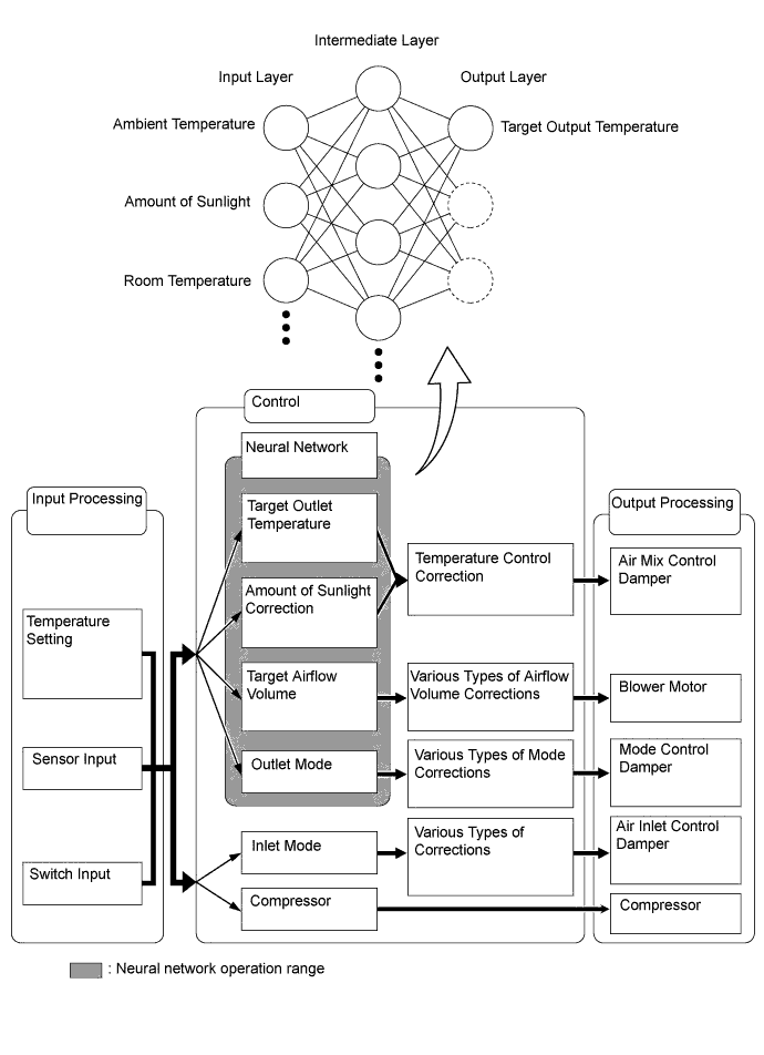
Previously, in automatic air conditioning systems without neural network control, the air conditioning amplifier determined the required outlet air temperature and blower air volume in accordance with the calculation formula had been obtained based on information received from the sensors. However, because the senses of a person are rather complex, a given temperature is sensed differently, depending on the environment in which the person is situated. For example, a given amount of solar radiation can feel comfortably warm in a cold climate, or extremely uncomfortable in a hot climate. Therefore, as a technique for performing a higher level of control, a neural network is used in the automatic air conditioning system. With this technique, the data that has been collected under varying environmental conditions is stored in the air conditioning amplifier. The air conditioning amplifier can then perform control in a way that provides enhanced air conditioning comfort.
-
The neural network control consists of neurons in the input layer, intermediate layer and output layer. The input layer neurons process the input data of the ambient temperature, the amount of sunlight, and the room temperature based on the outputs of the switches and sensors, and output them to the intermediate layer neurons. Based on this data, the intermediate layer neurons adjust the strength of the links among the neurons. The sum of these is then calculated by the output layer neurons in the form of the required outlet temperature, solar correction, target airflow volume and outlet mode control volume. Accordingly, the air conditioning amplifier controls the servo motors and blower motor in accordance with the control volumes that have been calculated by the neural network control.
-
-
Climate Concierge Control
-
When the air conditioning system, seat heater system and climate control seat system are controled in auto mode, the air conditioning amplifier assembly automatically controls the air conditioning system, seat heater system and climate control seat blower unit.
-
When the air conditioning system is heater mode control, the air conditioning amplifier assembly operates the seat heater system.
-
When the air conditioning system is cooler mode control, the air conditioning amplifier assembly operates the climate control seat system.
-
-
ECO Drive Mode Control
-
Under the control of the ECO drive mode, the air conditioning amplifier assembly restricts the air conditioning system performance under specified conditions, thus improving fuel economy.
-
The ECO drive mode control is activated when the combination switch assembly (drive mode selector) is operated, and then restricts the air conditioning system performance as described below:
Control Outline Inside/outside Air Switch Control Automatically switches the air inlet port to the internal air circulation mode when the outside air temperature is equal to or higher than a predetermined temperature and reduces the power consumption. Blower Level Control Sets the blower level in AUTO mode lower than normal, and suppresses the power consumption. Seat Heater Control When the ECO drive mode is selected, the air conditioning amplifier assembly turns on the front seat heater system in accordance with the air outlet mode (front seat control mode or driver seat control mode), outside temperature and room temperature. For details, refer to the seat heater system.
-
-
Electric Power Control
-
When the vehicle voltage is below the specified level, the air conditioning amplifier assembly, save the power source of some systems, that are PTC heater, seat heater and climate control seat, in accordance with the signal from ECM.
-
When the electric power control is operating, the combination meter assembly warns the driver by indicating a message "Operation of Electrical Items Restricted." on the multi-information display and illuminates the master warning light when receiving signals from the air conditioning amplifier assembly.
-
-
Automatic Recirculation Control
-
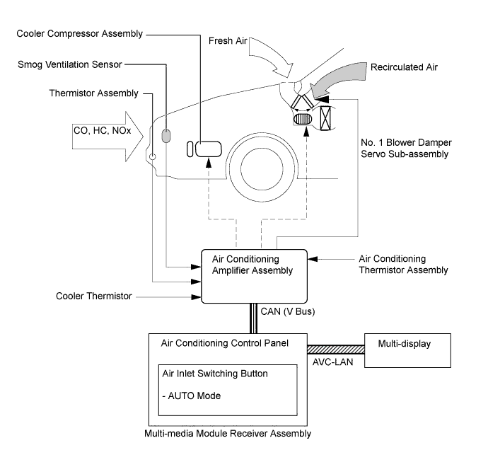
When the automatic recirculation control is operating, the air conditioning amplifier assembly automatically changes air inlet mode to fresh air or recirculate air mode based on signals from the smog ventilation sensor, thermistor assembly, cooler thermistor and air conditioning thermistor assembly when AUTO air inlet mode is selected.
-
The air conditioning amplifier assembly detects harmful elements (CO, HC and NOx) based on smog ventilation sensor signals and automatically switches air inlet mode to recirculate air mode to prevent such harmful elements from entering the cabin.
-
The air conditioning amplifier assembly detects the room temperature based on a cooler thermistor signal and automatically switches air inlet mode to recirculate air mode to prevent the room temperature from becoming too high.
-
The air conditioning amplifier assembly detects outside temperature and room humidity based on a thermistor assembly and air conditioning thermistor assembly signal and automatically switches air inlet mode to fresh air mode to prevent the windshield from fogging up.
Tech Tips
The smog ventilation sensor cannot detect elements such as smoke from a bonfire or factory exhaust, foul or animal odors, and dirt or dust particles. Therefore, air inlet mode is not switched in accordance with those elements. Depending on the direction of the wind, the smog ventilation sensor might not be able to detect the undesirable elements (CO, HC and NOx), allowing them to enter the cabin.
-
-
-
Pollen Removal Mode Control
-
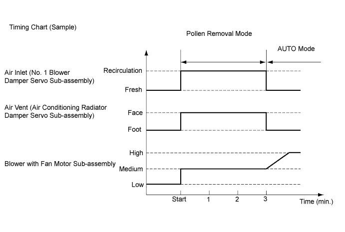
When the pollen removal switch is pressed, the pollen removal mode control is activated. Then, the air vent is switched to the FACE mode and recirculated pollen-free air flows around the upper body areas of the driver and front passenger.
-
When the pollen removal switch signal is received by the air conditioning amplifier assembly, the air conditioning amplifier assembly controls the No. 1 blower damper servo subassembly, air conditioner radiator damper servo and blower with fan motor sub-assembly as shown in the timing chart below.
-
This control usually operates for approximately 3 minutes. However, when the outside temperature is low, the control will operate for approximately 1 minute.
-
After this control stops operating, the air conditioning amplifier assembly controls the air conditioning system using AUTO mode.
-
-
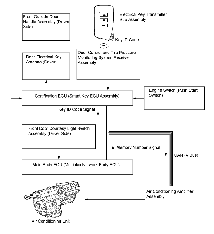
Memory Call Control
-
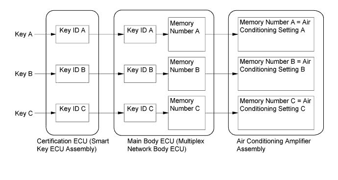
The air conditioning amplifier assembly stores the air conditioning settings for each memory number when the engine switch is turned off.
-
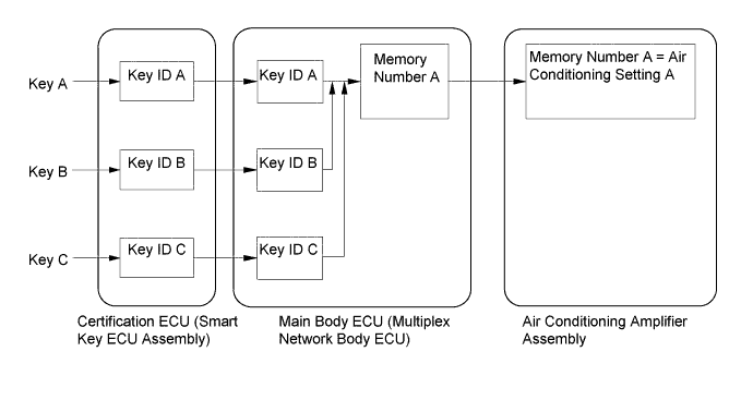
The main body ECU (multiplex network body ECU) converts the key ID code into a memory number, stores it and sends the converted signal to the air conditioning amplifier assembly.
-
The air conditioning amplifier assembly stores the memory number and air conditioning settings.
-
When the doors are unlocked, the certification ECU (smart key ECU assembly) recognizes the key ID code and sends it to the main body ECU (multiplex network body ECU).
-
Upon receiving the key ID code signal, the main body ECU (multiplex network body ECU) converts the signal into a memory number signal and sends it to the air conditioning amplifier assembly.
-
Then the air conditioning amplifier assembly recalls the stored air conditioning settings based on the memory number signal when the engine switch is turned on (IG).
-
The following air conditioning system settings can be memorized:
Setting Condition Air Conditioning Switch On or Off AUTO Switch On or Off Temperature Setting Driver LO, 16°C to 32°C (65°F to 85°F) or HI Front Passenger LO, 16°C to 32°C (65°F to 85°F) or HI Rear Passenger* LO, 16°C to 32°C (65°F to 85°F) or HI Blower Fan Speed Level 1 to 7 Air Inlet Mode Fresh or Recirculate Air Outlet Mode Face, Bi-level, Foot, Foot and Defroster or Defroster Dual or 3-zone* Switch On or Off
-
*: Models with 3-zone temperature control
Tech Tips
-
Memory call control of the air conditioning system can be canceled or re-enabled using the Global TechStream (GTS).
-
The main body ECU (multiplex network body ECU) can store a maximum of 3 memory numbers.
-
The memory call function recalls the key ID that was recognized when the door was unlocked. This happens even when the user brings 2 keys or more, or the user uses different keys to unlock the door and to turn the engine switch on (IG).
-
Using the GTS, the main body ECU (multiplex network body ECU) can be made to convert the ID numbers of different keys to a desired memory number. Therefore, all key IDs can be converted to an identical memory number, or 2 memory numbers can be divied among 3 keys.
-
For details about key ID code registration, refer to the Repair Manual.
-
-
-
-
CONSTRUCTION
-
Air Conditioning Control Panel
-
A push-button type air conditioning control panel integrated with a multi-media module receiver assembly is used.
-
Temperature control switches for the driver and front passenger are provided on the air conditioning control panel to enhance their ease of use.
-
The air conditioning status is displayed on the multi display.
-
Along with the use of pollen removal mode, a pollen removal switch is provided on the multi display.
-
On models with No. 1 ion generator sub-assembly, the [nanoe] switch is provided on the multi display.
-
In addition to the air conditioning control panel, the remote touch (remote operation switch) is used, ensuring remote control operation of items on the multi display and allowing for excellent operability and display visibility.
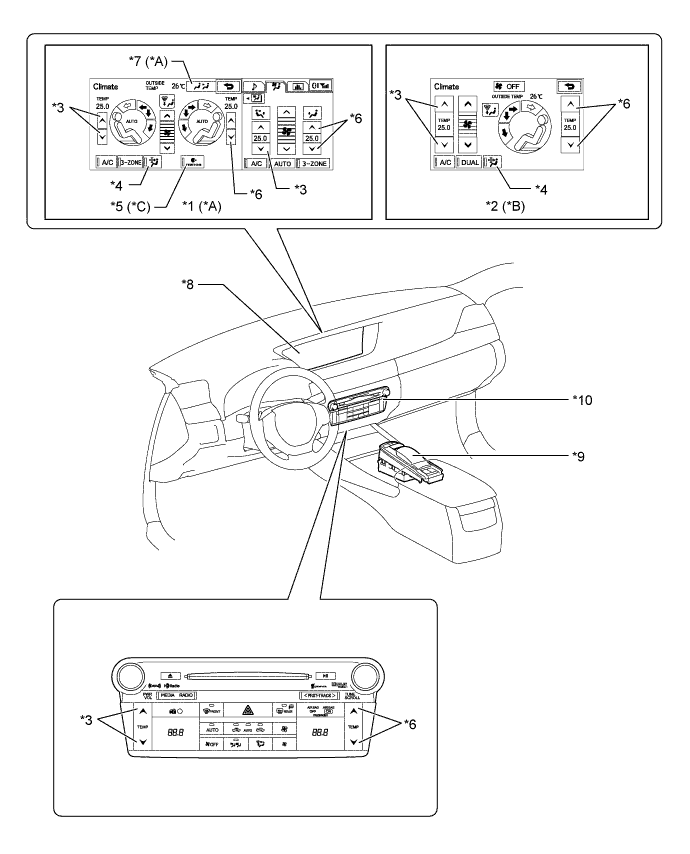
Text in Illustration *A Models with 3-zone Temperature Control *B Models with Left and Right Independent Temperature Control *C Models with No. 1 Ion Generator Sub-assembly - - *1 Accessory Meter Assembly (Models with 12.3-inche Display) *2 Multi-display (Models with 8-inch Display) *3 Temperature Control Switch (Driver Side) *4 Pollen Removal Switch *5 [nanoe] Generator Switch *6 Temperature Control Switch (Front Passenger Side) *7 Rear Control Mode Switch *8 Multi-display *9 Remote Touch (Remote Operation Switch) *10 Multi-media Module Receiver Assembly
-
-
Cooler Control Switch Panel
-
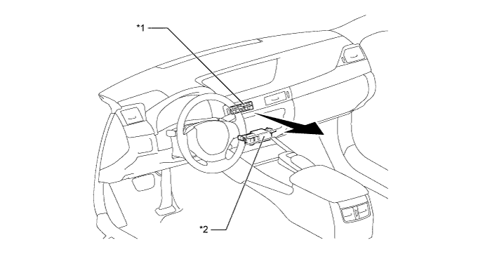
A cooler control switch panel, which can be used to switch the mode of the rear air conditioning system or adjust the temperature from the rear seats, is used on models with 3-zone temperature control, and is located in the rear seat center armrest.
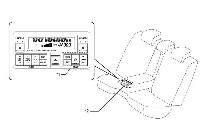
Text in Illustration *1 Rear Air Conditioning Switch Section *2 Cooler Control Switch Panel
-
-
Air Conditioning Unit
-
The air conditioning unit consists of the No. 1 cooler evaporator sub-assembly, No. 1 heater radiator unit sub-assembly, servo motors, evaporator temperature sensor (No. 1 cooler thermistor) and blower with fan motor sub-assembly.
-
The No. 1 cooler evaporator sub-assembly and No. 1 heater radiator unit sub-assembly are mounted transversely to achieve a compact and lightweight form.
-
A bus connector is used in the wire harness connection, which connects the servo motor to the air conditioning amplifier assembly.
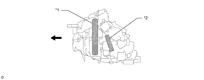
Text in Illustration *1 No. 1 Cooler Evaporator Sub-assembly *2 No. 1 Heater Radiator Unit Sub-assembly 
Front - - -
An inside-and-outside dual air layer type air conditioning unit is used. This type of air conditioning unit introduces outside air to the upper side and circulates inside air to the lower side, thus achieving antifogging performance and ventilation loss reduction.
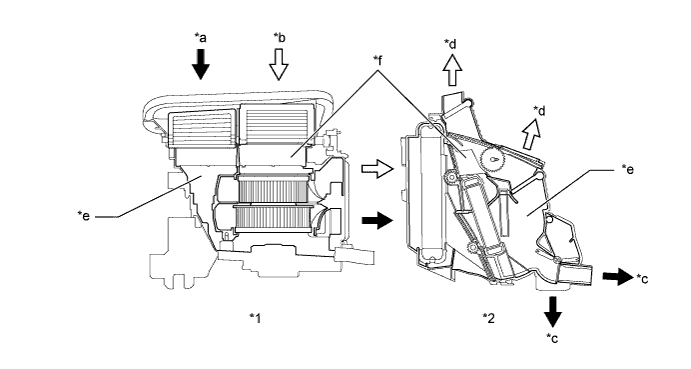
Text in Illustration *1 Blower Assembly *2 Air Conditioning Radiator Assembly *a Introduces Inside Air *b Introduces Outside Air *c Blows Inside Air *d Blows Outside Air *e Lower Layer *f Upper Layer -
Sliding doors are used for the air mix control doors (upper layer side and lower layer side) and mode control door (upper layer side), thus making the air conditioning radiator assembly more compact.
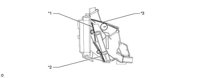
Text in Illustration *1 Air Mix Control Door (Upper Layer Side) *2 Air Mix Control Door (Upper Layer Side) *3 Mode Control Door (Upper Layer Side) - - -
A mode control door (DEF) exclusive for the defroster is installed in the air conditioning radiator assembly, thus making it possible for air to be blown from the defroster nozzle even in bi-level mode.
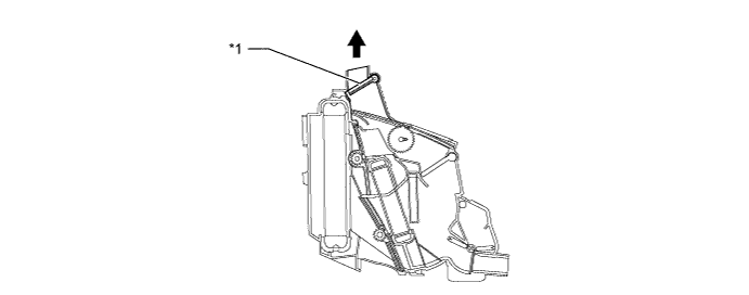
Text in Illustration *1 Mode Control Door (DEF) - - To Defroster Nozzle - -
-
-
No. 1 Cooler Evaporator Sub-assembly
-
A Revolutionary super-slim Structure (RS) type evaporator is used. Placing the tanks at the top and the bottom of the evaporator and using a micropore tube construction provides the following benefits:
-
Improved heat exchange efficiency
-
More uniform temperature distribution
-
A thinner evaporator
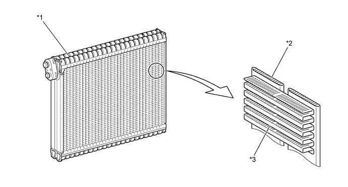
Text in Illustration *1 Tank *2 Micropore Tube *3 Cooling Fin - - -
-
-
Evaporator Temperature Sensor (No. 1 Cooler Thermistor)
-
The evaporator temperature sensor (No. 1 cooler thermistor) detects the temperature of the cooled air immediately past the evaporator in the form of resistance changes, and outputs this data to the air conditioning amplifier assembly.
-
-
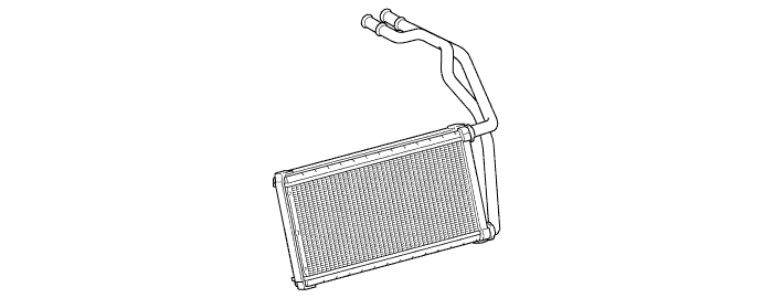
No. 1 Heater Radiator Unit Sub-assembly
-
The compact, lightweight and highly efficient Straight Flow Aluminum (SFA)-II type No. 1 heater radiator unit sub-assembly is used for the air conditioning system.
-
-
Blower with Fan Motor Sub-assembly
-
The blower with fan motor sub-assembly has a built-in blower controller which is controlled by the air conditioning amplifier assembly.
-
A brushless motor is used for the blower with fan motor sub-assembly. This achieves low noise and better usage of space, and enhances characteristics of the blower motor, which enables blower level to be increased.
-
Along with the usage of the inside-and-outside dual air layer type air conditioning unit, a dual step type sirocco fan with an integrated upper layer fan and lower layer fan is used for the blower with fan motor sub-assembly.
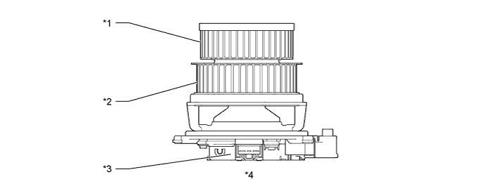
Text in Illustration *1 Upper Layer Fan *2 Lower Layer Fan *3 Built-in Blower Controller *4 Blower with Fan Motor Sub-assembly
-
-
Bus Connector
-
A bus connector is used in the wire harness connection, which connects the servo motor from the air conditioning amplifier assembly.
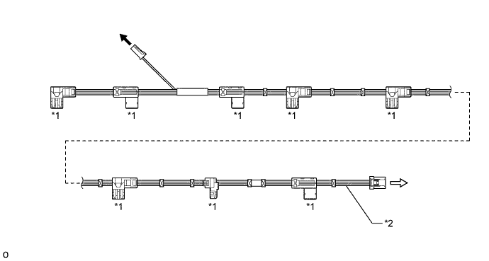
Text in Illustration *1 Bus Connector *2 Air Conditioning Harness Assembly To Evaporator Temperature Sensor (No. 1 Cooler Thermistor) 
To Air Conditioning Amplifier Assembly -
The bus connector has a built-in driver IC with a position detection function that communicates with each servo motor connector and actuates the servo motor. This enables bus communication for the servo motor wire harness with a more lightweight construction and a reduced number of wires.
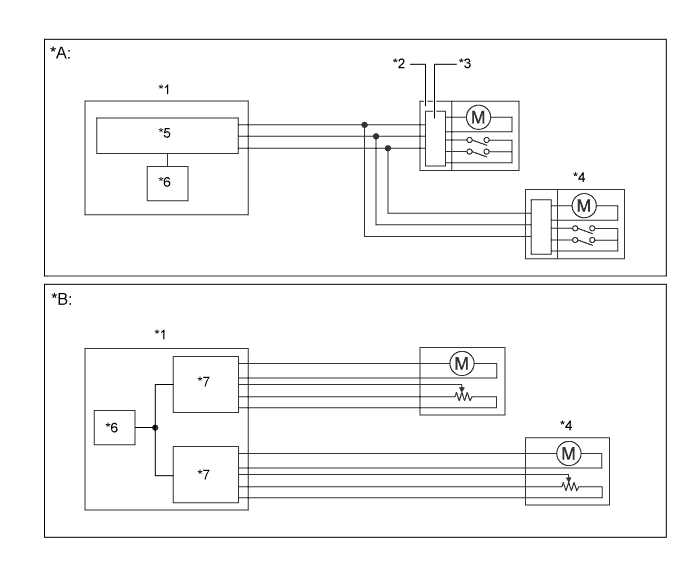
Text in Illustration *A Models with Bus Connector *B Models without Bus Connector *1 Air Conditioning Amplifier Assembly *2 Bus Connector *3 Communication Driver IC *4 Servo Motor *5 Communication IC *6 CPU *7 Driver IC - -
-
-
Servo Motor
-
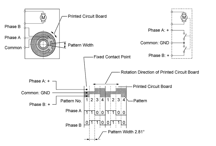
In contrast to the previous type that detects the position by way of a potentiometer voltage, the pulse pattern type servo motor detects the relative position by way of the 2-bit on/off signals.
-
The forward and reverse revolutions of this motor are detected by way of 2 phases, A and B, which output 4 types of patterns. The air conditioning amplifier assembly counts the number of pulse patterns in order to determine the stopped position.
-
-
Clean Air Filter (Air Refiner Element)
-
An air refiner element is used, which can remove odors from the cabin and exhaust gases. Activated charcoal is used for odor reduction, and the life of the air refiner has been prolonged by reducing the amount of desorbing odor which has been already absorbed once. In addition, the fixing material used to adhere activated charcoal to the air refiner element has been optimized and pressure loss reduction has been aimed for in the activated charcoal layer, thus enabling a finer non-woven fabric to achieve removal of micro particles such as pollen.
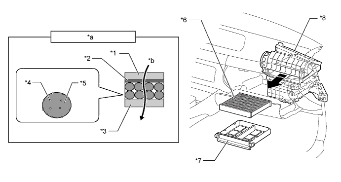
Text in Illustration *1 Non-woven Fabric (Upper Flow Side) *2 Fixing Material (in Sheet Form) *3 Non-woven Fabric (Lower Flow Side) *4 Fixing Material (in Particle Form) *5 Activated Charcoal *6 Air Refiner Element *7 Case *8 Blower Assembly *a Filter Cross-section *b Airflow
-
-
Cooler Condenser Assembly
-
A Multi-Flow (MF) type condenser is used. The cooler condenser assembly consists of 2 cooling portions: a condensing portion and a super-cooling portion. These portions are integrated with a gas-liquid separator (modulator). This cooler condenser assembly uses a sub-cool cycle that offers excellent heat-exchange performance.
-
In the sub-cool cycle, after the refrigerant passes through the condensing portion of the condenser, both the liquid refrigerant and the gaseous refrigerant that could not be liquefied are cooled again in the super-cooling portion. Thus, the refrigerant is sent to the evaporator in an almost completely liquefied state.
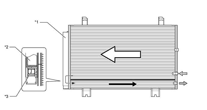
Text in Illustration *1 Modulator *2 Cooler Dryer *3 Filter - - Condensing Portion Super-cooling Portion 
Gaseous Refrigerant 
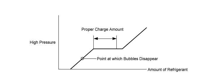
Liquid Refrigerant Tech Tips
The point at which the air bubbles disappear in the refrigerant of the sub-cool cycle is lower than the proper amount of refrigerant with which the system must be filled. Therefore, if the system is recharged with refrigerant based on the point at which the air bubbles disappear, the amount of refrigerant would be insufficient. As a result, the cooling performance of the system would be affected. Overcharging the system with refrigerant will also lead to reduced performance. For the proper method of verifying the amount of refrigerant and for instructions on how to recharge the system with refrigerant. For details, refer to the Repair Manual.
-
-
Cooler Compressor Assembly
-
The cooler compressor assembly is a continuously variable capacity type air conditioning compressor. Its capacity can be varied in accordance with the cooling load of the air conditioning system.
-
The cooler compressor assembly consists of a pulley, shaft, lug plate, swash plate, piston, shoe, crank chamber, cylinder, air conditioning lock sensor, solenoid control valve with builtin Crank chamber to Suction passage (CS) valve, air conditioning mass flow sensor, oil separator and variable suction side throttle.
-
The oil separator consists of an oil separator chamber and an oil separator cylinder.
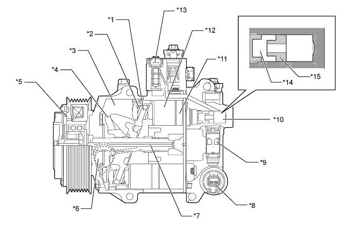
Text in Illustration *1 Swash Plate *2 Shoe *3 Crank Chamber *4 Lug Plate *5 Pulley
- Magnetic Clutch
*6 Air Conditioning Lock Sensor *7 Shaft *8 Solenoid Control Valve with Built-in CS Valve *9 Variable Suction Side Throttle *10 Oil Separator *11 Cylinder *12 Piston *13 Air Conditioning Mass Flow Sensor *14 Oil Separator Chamber *15 Oil Separator Cylinder - -
-
-
Room Temperature Sensor (Cooler Thermistor)
-
The room temperature sensor detects the room temperature based on changes in the resistance of its built-in thermistor. This signal is used by the air conditioning amplifier assembly.
-
-
Humidity Sensor (Air Conditioning Thermistor Assembly)
-
A humidity sensor, in which the glass temperature sensor, glass surroundings temperature sensor and glass humidity sensor are integrated, is used.
-
The glass temperature sensor detects the surface temperature of the windshield using the built-in thermistor attached to the back of the sensor board, and outputs the signal to the air conditioning amplifier assembly.
-
The gases surroundings temperature sensor detects the air temperature near the windshield using the built-in thermistor, and outputs the signal to the air conditioning amplifier assembly.
-
The glass humidity sensor converts a change in the electrostatic capacity between the electrodes by allowing the humidity-sensing film to absorb and desorb moisture in the cabin, and outputs the signal to the air conditioning amplifier assembly.
-
-
Ambient Temperature Sensor (Thermistor Assembly)
-
The ambient temperature sensor detects the ambient temperature based on changes in the resistance of its built-in thermistor. This signal is used by the air conditioning amplifier assembly.
-
-
Automatic Light Control Sensor
-
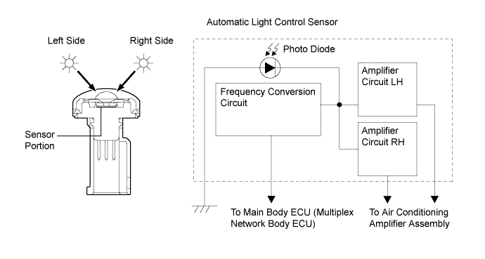
The automatic light control sensor consists of a photo diode, 2 amplifier circuits and a frequency converter circuit.
-
The automatic light control sensor detects (in the form of changes in the current that flows through the built-in photo diode) the changes in the amount of sunlight from its left and right sides (2 directions) and outputs these sunlight strength signals to the air conditioning amplifier assembly for the automatic air conditioning control.
-
-
Air Conditioning Pressure Sensor
-
The air conditioning pressure sensor detects the refrigerant pressure and outputs it to the air conditioning amplifier assembly in the form of voltage changes.
-
-
[nanoe] Generator (Models with No. 1 Ion Generator Sub-assembly)
-
A [nanoe] generator (No. 1 ion generator sub-assembly) is provided to enhance the air quality and comfort in the cabin.
-
The [nanoe] outlet of the [nanoe] generator is attached under the multi-media module receiver assembly. This allows [nanoe] to be released together with air from the driver side center register.
-
The [nanoe] generator is controlled by the air conditioning amplifier assembly and operates when [nanoe] generator switch is pressed.
Text in Illustration *1 Center Register (Driver Side) *2 [nanoe] Generator (No. 1 Ion Generator Sub-assembly) Note
-
The [nanoe] generator uses a high voltage, which is hazardous. Therefore, if the [nanoe] generator requires repairs, be sure to have them done at a Lexus dealer.
-
Do not apply any type of spray (such as a cleaning solvent or hair spray) or stick any foreign matter into the [nanoe] ion outlet, as this could cause improper operation or a malfunction.
-
It is normal for the [nanoe] generator to emit a slight sound during operation. This sound is created when electrons collide with the electrode while [nanoe] are being generated.
-
-
-
-
OPERATION
-
Mode Position and Door Operation
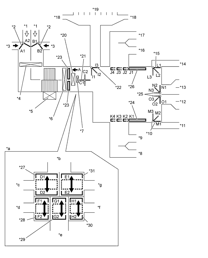
Text in Illustration *1 Recirculated Air *2 Air Inlet Control Door *3 Fresh Air *4 Air Refiner Element *5 Blower with Fan Motor Sub-assembly *6 No. 1 Cooler Evaporator Sub-assembly *7 Quick Heater Assembly *8 Side Register (Front Passenger Side) *9 Center Register (Front Passenger Side) *10 Mode Control Door (for Front Passenger Footwell Register) *11 Front Footwell Register Duct (Front Passenger Side) *12 Rear Footwell Register Duct *13 Console Box Register *14 Front Footwell Register Duct (Driver Side) *15 Mode Control Door (for Driver Footwell Register) *16 Center Register (Driver Side) *17 Side Register (Driver Side) *18 Side Defroster *19 Center Defroster *20 No. 1 Heater Radiator Unit Sub-assembly *21 Inside-and-outside Dual Air Layer Control Door *22 Mode Control Door (for Defroster) *23 Air Mix Control Door *24 Mode Control Door (for Front Passenger Center and Side Register) *25 Mode Control Door (for Console Box Register and Rear Passenger Footwell Register Duct) *26 Mode Control Door (for Driver Center and Side Register) *27 Air Mix Control Door (for Driver Side Upper Layer) *28 Air Mix Control Door (for Driver Side Lower Layer) *29 Air Mix Control Door (for Rear Passenger) *30 Air Mix Control Door (for Front Passenger Lower Layer) *31 Air Mix Control Door (for Front Passenger Side Upper Layer) - - *a View from A *b To Center and Side Defrosters *c To Driver Side Center and Side Registers *d To Driver Side Footwell Register Duct *e To Console Box Register and Rear Footwell Register Duct *f To Front Passenger Side Footwell Register Duct *g To Front Passenger Side Center and Side Register - - Mode Position and Door Operation Control Door Operation Position*1 Door Position Operation Air Inlet Control Door FRESH A2, B1 Brings in fresh air. RECIRCULATION A1, B2 Recirculates internal air. Inside-and-outside Dual Air Layer Control Door - (Auto Control) C1 - C2 Separates or integrates the upper layer and lower layer in response to the control conditions to control the inside-and-outside dual air layers. Air Mix Control Door MAX COLD to MAX HOT Temperature Setting D1 - D2*2
E1 - E2*3
F1 - F2*4
G1 - G2*5
H1 - H2*6
Varies the mixture ratio of warm air and cool air in order to continuously regulate the temperature between hot and cold. Mode Control Door (for All Seat Control Modes) 
FACE J1, K1, L1, M1, N3, O1, I3, I2*7 Air blows out of the front center register, side register and console box register. 
BI-LEVEL J2, K2, L2, M2, N2, O2, I3, I2*7 Air blows out of the front center register, side register, console box register and front and rear footwell register ducts. Air may blow out from the center defroster and side defroster depending on the cabin environment (I2). 
FOOT J3, K3, L3, M3, N2, O3, I2 Air blows out of the front footwell register and rear footwell register ducts. In addition, air blows out slightly from the front center register, side register and console box register. Air blows out slightly from the center defroster and side defroster. 
FOOT AND DEFROSTER J3, K3, L2, M2, N2, O2, I1 Defrosts the windshield through the center defroster and side defroster, while air is also blown out from the front footwell register and rear footwell register ducts. In addition, air blows out slightly from the front center register, side register and console box register. 
DEFROSTER J4, K4, L1, M1, N1, O1, I1 Defrosts the windshield through the center defroster and side defroster ducts. Mode Control Door (for Front Seat Control Modes)*8 FACE J1, K1, L1, M1, N1, O1, I3, I2*7 Air blows out of the front center register and side register BI-LEVEL J2, K2, L2, M2, N1, O1, I3, I2*7 Air blows out of the front center register, side register and front footwell register ducts. Air may blow out from the center defroster and side defroster depending on the cabin environment (I2). FOOT J3, K3, L3, M3, N1, O1, I2 Air blows out of the front footwell register. In addition, air blows out slightly from the front center register and side register. Air blows out slightly from the center defroster and side defroster. FOOT AND DEFROSTER J3, K3, L2, M2, N1, O1, I1 Defrosts the windshield through the center defroster and side defroster, while air is also blown out from the front footwell register. In addition, air blows out slightly from the front center register and side register. DEFROSTER J4, K4, L1, M1, N1, O1, I1 Defrosts the windshield through the center defroster and side defroster ducts. Mode Control Door (for Driver Seat Control Modes)*9 FACE J1, K4, L1, M1, N1, O1, I3, I2*7 Air blows out of the driver side front center register and side register. BI-LEVEL J2, K4, L2, M1, N1, O1, I3, I2*7 Air blows out of the driver side front center register, side register and front footwell register ducts. Air may blow out from the center defroster and side defroster depending on the cabin environment (I2). FOOT J3, K2, L3, M1, N1, O1, I2 Air blows out of the driver side front footwell register. In addition, air blows out slightly from the front driver side center register and side register. Air blows out slightly from the center defroster and side defroster. FOOT AND DEFROSTER J3, K4, L2, M1, N1, O1, I1 Defrosts the windshield through the center defroster and side defroster, while air is also blown out from the front driver side footwell register. In addition, air blows out slightly from the front driver side center register and side register. Tech Tips
*1: The table shows the left and right air outlets and rear seat air outlets operating simultaneously. On the models with 3-zone temperature control, each seat air outlet can be switched independently.
*2: For driver side front register and side register
*3: For front passenger side front register and side register
*4: For driver side front footwell register
*5: For console box register and rear footwell register ducts
*6: For front passenger side front footwell register
*7: On models for Europe, when the volume of air from the center register and side register is large, air blows out slightly from the center defroster and side defroster.
*8: When the rear seat air outlets are stopped by the left and right independent temperature control, or when front seat control mode is turned on through the S-FLOW control of the 3-zone temperature control.
*9: The driver seat control mode is turned on by the S-FLOW control of the 3-zone temperature control.
-
Air Outlets and Airflow Volume (for All Seat Control Modes)
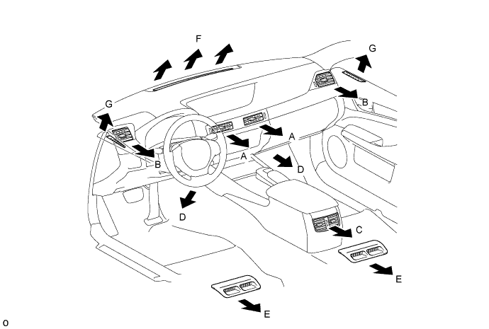
Indication Mode Face Footwell Defroster Center Side Rear Front Rear Center Side A B C D E F G FACE-U*1 
- - - - 
*3
*3
FACE-L*1 
- - *3
*3
FACE-R*1, *2 
- - - - *3
*3
BI-LEVEL*1, *2 *3, *4
*3, *4
FOOT-D*1 FOOT-R*1, *2 FOOT-F*1 FOOT AND DEFROSTER *1, *2 DEFROSTER *1, *2 - - - - - Tech Tips
The size of the circle ○ indicates the proportion of air flow volume.
*1: When each mode is turned on by automatic control. In addition, -U, -L and -R in FACE mode are selected by the automatic control and -D, -R or -F in FOOT mode as well.
*2: When each mode is selected by a manual operation.
*3: On models for Europe, when the volume of air from the center register and side register is large, air blows out slightly from the center defroster and side defroster.
*4: Air may blow out from the defroster in response to the cabin temperature and moisture, and outside temperature conditions.
-
Air Outlets and Airflow Volume (for Front Seat Control Modes)
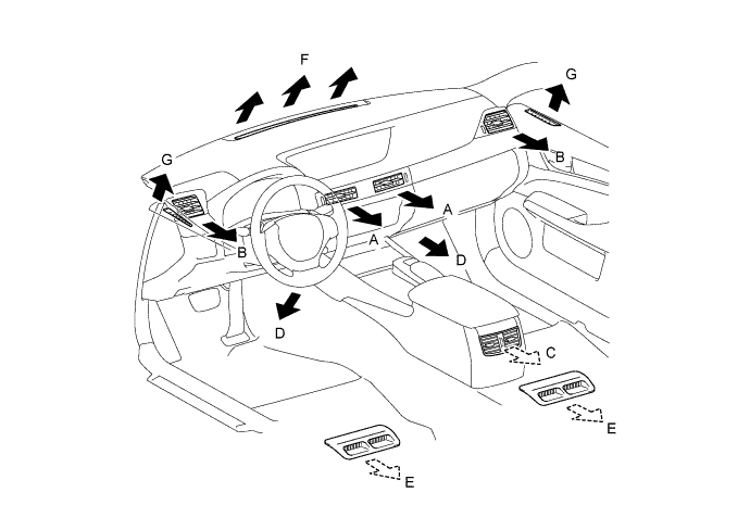
Indication Mode Face Footwell Defroster Center Side Rear Front Rear Center Side A B C D E F G FACE-U*1 - - - - - *3
*3
FACE-L*1 - - - - *3
*3
FACE-R*1, *2 - - - - - *3
*3
BI-LEVEL*1, *2 - - *3, *4
*3, *4
FOOT-D*1 - - FOOT-R*2 - - FOOT-F*1 - - FOOT AND DEFROSTER *1, *2 - - DEFROSTER *1, *2 - - - - - Tech Tips
The size of the circle ○ indicates the proportion of air flow volume.
*1: When each mode is turned on by automatic control. In addition, -U, -L and -R in FACE mode are selected by the automatic control and -D, -R or -F in FOOT mode as well.
*2: When each mode is selected by a manual operation.
*3: On models for Europe, when the volume of air from the center register and side register is large, air blows out slightly from the center defroster and side defroster.
*4: Air may blow out from the defroster in response to the cabin temperature and moisture, and outside temperature conditions.
-
Air Outlets and Airflow Volume (for Driver Seat Control Modes)
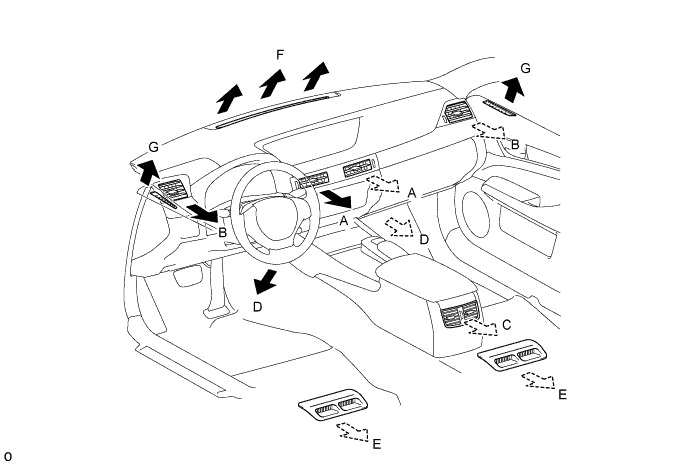
Indication Mode Face (Only for Driver Side) Footwell (Only for Driver Side) Defroster Center Side Rear Front Rear Center Side A B C D E F G FACE-U*1 - - - - - *3
*3
FACE-L*1 - - - - *3
*3
FACE-R*1, *2 - - - - - *3
*3
BI-LEVEL*1, *2 - - *3, *4
*3, *4
FOOT-D*1 - - FOOT-R*1, *2 - - FOOT-F*1 - - FOOT AND DEFROSTER *1, *2 - - Tech Tips
The size of the circle ○ indicates the proportion of air flow volume.
*1: When each mode is turned on by automatic control. In addition, -U, -L and -R in FACE mode are selected by the automatic control and -D, -R or -F in FOOT mode as well.
*2: When each mode is selected by a manual operation.
*3: On models for Europe, when the volume of air from the center register and side register is large, air blows out slightly from the center defroster and side defroster.
*4: Air may blow out from the defroster in response to the cabin temperature and moisture, and outside temperature conditions.
-
Cooler Compressor Operation
-
Variable Capacity Operation
-
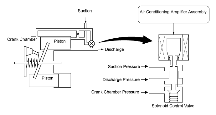
A solenoid control valve is connected to the suction passage discharge passage and crank chamber passage.
-
The solenoid control valve operates under duty cycle control in accordance with the signals from the air conditioning amplifier assembly.
-
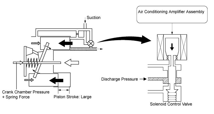
When the solenoid control valve closes (solenoid coil is energized), a difference in pressure is created and the pressure in the crank chamber decreases. Then, the pressure that is applied to the right side of the piston becomes greater than the pressure that is applied to the left side of the piston. This compresses the spring and tilts the lug plate. As a result, the piston stroke increases and the discharge capacity increases.
-
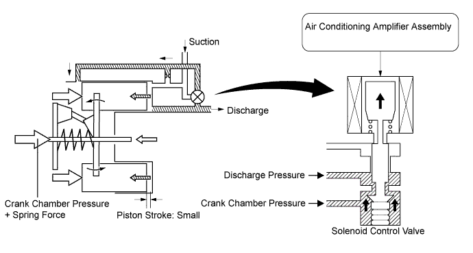
When the solenoid control valve opens (solenoid coil is not energized), the difference in pressure disappears. Then, the pressure that is applied to the left side of the piston becomes the same as the pressure that is applied to the right side of the piston. Thus, the spring elongates and eliminates the tilt of the lug plate. As a result, the piston stroke is small, decreasing the discharge capacity.
-
-
Air Conditioning Lock Sensor Operation
-
The air conditioning lock sensor outputs a pulley rotation signal to the air conditioning amplifier assembly.
-
The air conditioning amplifier compares this signal with the engine speed signal sent from the ECM to judge if the cooler compressor assembly is locked. when the cooler compressor assembly is locked, the magnetic clutch is turned off.
-
-
Air Conditioning Mass Flow Sensor Operation
-
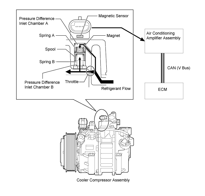
Using a spool that changes its position in accordance with the amount of refrigerant flow, the air conditioning mass flow sensor detects the amount of refrigerant flow.
-
The air conditioning mass flow sensor outputs a voltage by converting the change of magnetic flux that occurs due to the magnet that is installed on the spool.
-
The spool changes its position in accordance with the pressure difference between the pressure before and after the refrigerant flow throttle.
-
When the amount of refrigerant flow is small, the pressure difference between pressure difference inlet chamber A and B is low, allowing the force of spring B to push up the spool.
-
When the amount of refrigerant flow is large, the pressure difference between pressure difference inlet chamber A and B is high. The pressure difference overwhelms the force of spring B, and the spool moves down.
-
Based on the amount of refrigerant flow detected by the air conditioning flow sensor, the air conditioning amplifier and ECM cooperatively control the cooler compressor assembly and the engine.
-
-
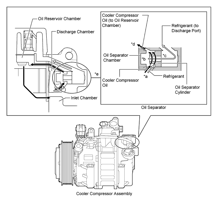
Oil Separator Operation
-
A mixture of refrigerant and cooler compressor oil flows into the oil separator chamber from the discharge chamber (*a).
-
The force of the refrigerant and oil mixture flow turns the oil separator cylinder, allowing the oil and refrigerant to be centrifugally separated (*b).
-
The separated refrigerant flows to the condenser through the discharge port (*c).
-
The separated oil circulates and lubricates the inside of the cooler compressor by flowing through the oil reservoir chamber, inlet chamber, cylinder and discharge chamber. In addition, the amount of oil that is discharged by the cooler compressor is suppressed (*d).
-
The oil separator is installed in the refrigerant passage to separate cooler compressor oil from the refrigerant that is discharged. This helps to prevent the cooler compressor oil from flowing into the air conditioning system and reducing cooling effectiveness (*e).
-
-
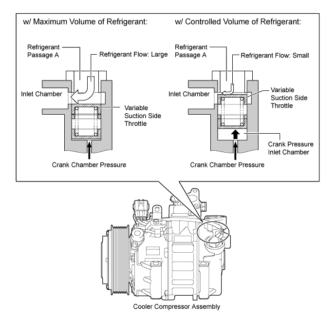
Variable Suction Side Throttle Operation
-
Refrigerant inlet pressure is applied to the top of the variable suction side throttle and crank chamber pressure to the bottom of the variable suction side throttle.
-
The pressure difference moves the variable suction side throttle up and down, expanding and contracting the refrigerant inlet passage.
-
When the refrigerant flow is at a maximum, the refrigerant inlet pressure is greater than the crank chamber pressure. This causes the variable suction side throttle to move down, fully opening the refrigerant inlet passage and lowering the refrigerant inlet resistance.
-
When the amount of refrigerant flow is controlled, the crank chamber pressure is greater than the refrigerant inlet pressure, raising the variable inlet throttle to contract the flow passage.
-
These controls suppress noise by reducing pulsation from the refrigerant inlet.
-
-
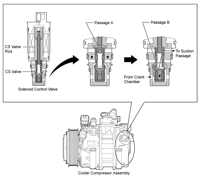
CS Valve Operation
-
The Crank chamber to Suction passage (CS) valve, built into the solenoid control valve, operates in accordance with the suction pressure. The CS valve consists of passage A and passage B.
-
If the vehicle is left parked for a long period, refrigerant may accumulate in the crank chamber due to the heat capacity difference.
-
The solenoid control valve is controlled by the air conditioning amplifier assembly. While the cooler compressor assembly is operating, the solenoid control valve pushes down the CS valve rod and open passage A.
-
Under the above condition, only if the refrigerant accumulates in the crank chamber, the crank chamber pressure will become high. As a result, the bellows will contract because of the pressure difference with its internal pressure (vacuum), and opens passage B.
-
This causes the accumulated refrigerant to be drawn in via passage A and B, clearing the accumulated refrigerant earlier and ensuring a more immediate cooling effect.
-
-
-
[nanoe] Generator Operation
-
The [nanoe] generator (No. 1 ion generator sub-assembly) gathers moisture in the air, generates [nanoe] by applying a high level of electric voltage and emits it from the driver side center register to the cabin.
-
Electrodes and a Peltier device are installed in the [nanoe] generator. The electrodes cooled by applying current to the Peltier device generate [nanoe] by applying a high level of electric voltage to water drops created by dew condensation.
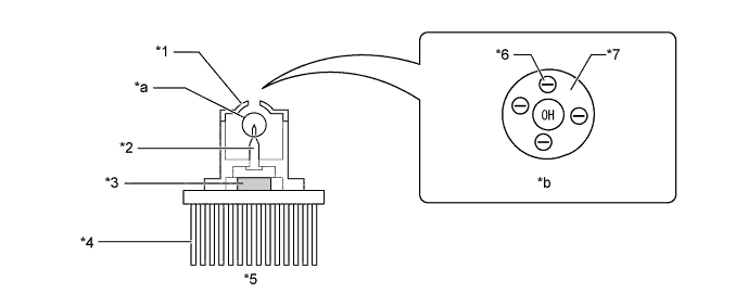
Text in Illustration *1 Counter Electrode *2 Electrode *3 Peltier Device *4 Heatsink *5 [nanoe] Generator (No. 1 Ion Generator Sub-assembly) *6 Electron *7 Water - - *a [nanoe] Generation Portion *b Image of [nanoe]
-
-