PRE-CRASH SAFETY SYSTEM DETAILS
-
FUNCTION OF MAIN COMPONENTS
Item Function Combination Meter Assembly PCS Warning Light Illuminates or flashes to warn the driver in accordance with signals from the seat belt control ECU or driving support ECU assembly. Multi-information Display Displays a warning message to inform or warn the driver of the system condition in accordance with signals from the seat belt control ECU or driving support ECU assembly. Master Warning Light Illuminates to warn the driver in accordance with signals from the seat belt control ECU or driving support ECU assembly. Multi Buzzer Sounds to warn the driver in accordance with signals from the seat belt control ECU or driving support ECU assembly when the system is malfunctioning. Millimeter Wave Radar Sensor Assembly Radiates millimeter radio wave radar forward, uses the reflected millimeter radio wave for detecting the presence of a vehicle ahead, the vehicle-to-vehicle distance and the relative speed, and then transmits this information to the driving support ECU assembly. Front Seat Outer Belt Assembly Seat Belt Motor Retracts the seat belt in accordance with signals received from the seat belt control ECU. Front Seat Inner Belt Assembly (Driver) Buckle Switch Detects the condition (verifies if the belt is fastened) of the driver seat belt and transmits a signal to the airbag sensor assembly. Front Seat Inner Belt Assembly (Passenger) Buckle Switch Detects the condition (verifies if the belt is fastened) of the front passenger seat belt and transmits a signal to the airbag sensor assembly. Airbag Sensor Assembly Transmits the condition (fastened or unfastened) of the driver and front passenger seat belts to the seat belt control ECU. Driving Support ECU Assembly Makes judgments on whether a collision is unavoidable based on the information received from the millimeter wave radar sensor assembly. It then outputs a seat belt operation signal and brake assist standby request signal and pre-crash brake request signal if required. Seat Belt Control ECU Receives a seat belt operation request signal from the driving support ECU or skid control ECU assembly and operates the seat belts. Brake Actuator Assembly Master Cylinder Pressure Sensor Detects the master cylinder pressure and transmits a signal to the skid control ECU Assembly. Skid Control ECU Assembly
-
Receives a brake assist standby request signal from the driving support ECU assembly and switches the brake assist to standby mode. When a stop light switch assembly signal is input, it activates the brake assist.
-
Receives a pre-crash brake request signal from the driving support ECU assembly, and then applies the brakes.
-
Determines if the brakes have been applied suddenly through signals received from the master cylinder pressure sensor, and outputs a seat belt operation signal to the seat belt control ECU.
-
Determines that the vehicle is out of control or that the brakes have been applied and outputs a seat belt operation signal to the seat belt control ECU.
-
Transmits vehicle speed signals to the driving support ECU assembly.
Stop Light Switch Assembly Detects if the brake pedal is depressed and transmits a signal to the skid control ECU assembly and driving support ECU assembly. Speed Sensor Detects speed of each wheel and transmits the signals to the skid control ECU assembly. Yawrate Sensor Detects the yaw rate and lateral/longitudinal deceleration of the vehicle and transmits the signal to the skid control ECU assembly and the driving support ECU assembly. Steering Sensor Detects the angle and direction of steering and transmits a signal to the skid control ECU assembly and the driving support ECU assembly. Precrash System Cancel Switch Assembly Disables the pre-crash system operation when the switch is turned on. The PCS warning light illuminates to show that the pre-crash system off. Skid Control Buzzer Assembly Sounds to warn the driver in accordance with signals from the skid control ECU assembly. Driver Monitor Camera Assembly*1 The driver monitor camera assembly monitors the face and eyelid of the driver and sends image data to the driver monitor ECU assembly. Driver Monitor ECU Assembly*1 The direction of the driver's face and eyelid is judged according to the data received from the driver monitor camera assembly and the data is sent to the driving support ECU assembly. Combination Meter Mirror ECU*2 Displays a warning message to inform or warn the driver of the system condition in accordance with signals from the combination meter assembly. Absorber Control ECU*3 Receives an AVS operation request signal from the driving support ECU assembly and operates the absorber control actuators. Absorber Control Actuator*3 Changes the damping force of the shock absorber assembly. Front Steering Control ECU*4 Receives a VGRS operation request signal from the driving support ECU assembly and operates the steering actuator assembly. Steering Actuator Assembly*4 Rotates to create the operating angle of the front steering. Rear Steering Control ECU Assembly*4 Receives a DRS operation request signal from the driving support ECU assembly and operates the rear steering link assembly. Rear Steering Link Assembly*4 Rotates to create the operating angle of the rear steering.
-
*1: Models with driver monitor camera
-
*2: Models with headup display
-
*3: Models with AVS system
-
*4: Models with Lexus dynamic handling system
-
-
OPERATING CONDITION
Operating Conditions When the driving support ECU assembly determines the high possibility of a collision, or an unavoidable collision with an obstacle in front of the vehicle.
The pre-crash seat belt also operates under the following conditions:
-
When the brakes are suddenly applied.
-
When the system determines a loss of vehicle control.
Non-operating Conditions
-
The relative speed of an oncoming vehicle is approx. 30 km/h (19 mph) or less.
-
Vehicle speed is approx. 5 km/h (4 mph) or less.
-
The front seat belt is not fastened.
-
The vehicle collides with an object that the millimeter wave radar sensor assembly cannot detect (plastic items, safety cones, etc.) or cannot detect in a stable manner (people, bicycles, motorcycles, trees, animals, snow fences, etc.).
-
The engine switch is off or on (ACC).
-
The multi-information display in the combination meter assembly shows warning messages.
-
The vehicle collides with an object located outside the detection area of the millimeter wave radar sensor assembly.
-
The pre-crash safety system operates in the following 3 situations: pre-crash (high possibility of frontal collision or unavoidable collision) situation, loss of vehicle control and sudden braking. The impact dampening components are as shown below:
Operation Operation Condition Impact Dampening Component Loss of Vehicle Control
-
Engine switch is on (IG).
-
Vehicle speed is approx. 30 km/h (19 mph) or more.
-
Seat belt is fastened.
Seat Belt Retract Operation Sudden Braking Pre-crash
-
Engine switch is on (IG).
-
Seat belt is fastened.
-
Vehicle speed is approx. 5 km/h (4 mph) or more.
-
Oncoming vehicle relative speed is approx. 30 km/h (19 mph) or more.
-
Seat Belt Retract Operation
-
AVS Operation
-
Engine switch is on (IG).
-
Vehicle speed is approx. 15 km/h (10 mph) or more.
-
Oncoming vehicle relative speed is approx. 15 km/h (10 mph) or more.
-
Pre-crash Warning Operation
-
Pre-crash Brake Operation*1
-
Engine switch is on (IG).
-
Vehicle speed is approx. 30 km/h (19 mph) or more.
-
Oncoming vehicle relative speed is approx. 30 km/h (19 mph) or more.
-
Seat belt is fastened.
-
Pre-crash Warning Operation
-
Pre-crash Brake Operation*
-
Seat Belt Retract Operation
-
AVS Operation*2
-
Lexus Dynamic Handling System Operation*3
-
Brake Assist Standby Condition
Pre-crash (Models with Driver Monitor Camera)
-
Engine switch is on (IG).
-
Vehicle speed is approx. 40 km/h (25 mph) or more.
-
Oncoming vehicle relative speed is approx. 40 km/h (25 mph) or more.
-
Seat belt is fastened.
-
Driver is not facing forward or eyelid are not open.
-
Pre-crash Warning Operation
-
Pre-crash Brake Operation*1
-
Seat Belt Retract Operation
-
AVS Operation*2
-
Lexus Dynamic Handling System Operation*3
-
Brake Assist Standby Condition
-
Pre-crash Alert Braking Operation
-
*1: Except models for Thailand and Taiwan
-
*2: Models with AVS system
-
*3: Models with Lexus dynamic handling system
-
-
When precrash system cancel switch assembly is turned on, the pre-crash safety system does not operate.
-
-
SYSTEM CONTROL
-
Loss of Vehicle Control
(1) While the vehicle is traveling at approx. 30 km/h (19 mph) or more, the skid control ECU assembly determines if skid recovery will be difficult based on the signals from the steering sensor, yawrate sensor and speed sensors. (2) The skid control ECU assembly sends a seat belt operation request signal to the seat belt control ECU. (3) The seat belt control ECU determines the seat belt motor operating conditions based on this signal and seat belt buckle switch signals. Then, it retracts the slack in the seat belts by operating the seat belt motors. (4) The seat belts return to a normal state when the relevant conditions of the vehicle have stabilized. 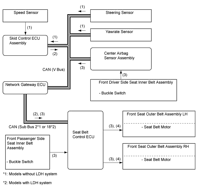
-
Sudden Braking
(1) While the vehicle is traveling at approx. 30 km/h (19 mph) or more, the skid control ECU assembly can determine a sudden braking condition based on the signals from the master cylinder pressure sensor, stop light switch assembly and speed sensors. (2) At this time, the skid control ECU assembly outputs a seat belt operation request signal to the seat belt control ECU. (3) The seat belt control ECU determines the seat belt motor operating conditions based on this signal and seat belt buckle switch signals. Then, it retracts the slack in the seat belts by operating the seat belt motors. (4) The seat belts return to a normal state when the brake pedal is released. 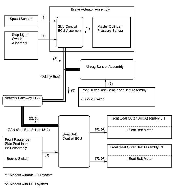
-
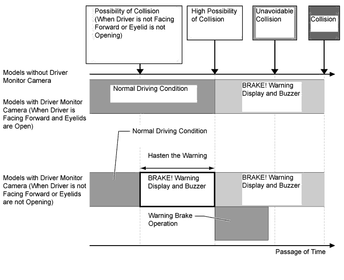
High Possibility of Collision or Unavoidable Collision
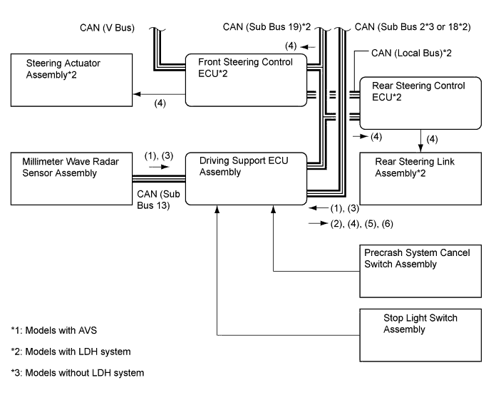
Driver is not Facing Forward or Eyelids are not Opening (Models with Driver Monitor Camera) (1) The driving support ECU assembly determines that the possibility of a collision based on the signals received from the millimeter wave radar sensor assembly, steering sensor, speed sensor and yawrate sensor. (2) If the driver monitor ECU assembly determines that the driver is not facing forward based on signals from the driver monitor camera, it transmits this information to the driving support ECU assembly. (3) The driving support ECU assembly transmits a BRAKE! warning display request signal to the combination meter assembly and a skid control buzzer assembly request signal and warning brake request signal to the skid control ECU assembly. (4) The driving support ECU assembly determines that the possibility of a collision is high based on the signals received from the millimeter wave radar sensor assembly, steering sensor, speed sensor and yawrate sensor. (5) The driving support ECU assembly transmits a warning brake request signal to the skid control ECU assembly. (6) The driving support ECU assembly determines that an unavoidable collision condition exists based on the signals received from the millimeter wave radar sensor assembly, speed sensor, steering sensor and yawrate sensor. (7) The driving support ECU assembly outputs a pre-crash brake assist request signal to the skid control ECU assembly. Upon receiving this signal, the skid control ECU assembly switches the brake assist to the standby condition. At the same time, the driving support ECU assembly outputs a steering assist request signal to the front and rear steering control ECU assembly. Upon receiving this signal, the front and rear steering control ECU switches the Lexus dynamic handling systems to the standby condition. (8) The driving support ECU assembly outputs an AVS request signal to the absorber control ECU. Upon receiving this signal, the absorber control ECU controls the absorber control actuators. (9) The driving support ECU assembly outputs a seat belt operation request signal to the seat belt control ECU and a pre-crash brake request signal to the skid control ECU assembly. (10) The seat belt control ECU determines the seat belt motor operation condition based on this signal and the seat belt buckle switch signal, and retracts the slack in the seat belts by operating the seat belt motors. At the same time, the skid control ECU assembly activates the brake actuator assembly as a pre-crash brake control and decelerates the vehicle. (11) If no collision occurs, the seat belts and the brake assist will return to their normal states. 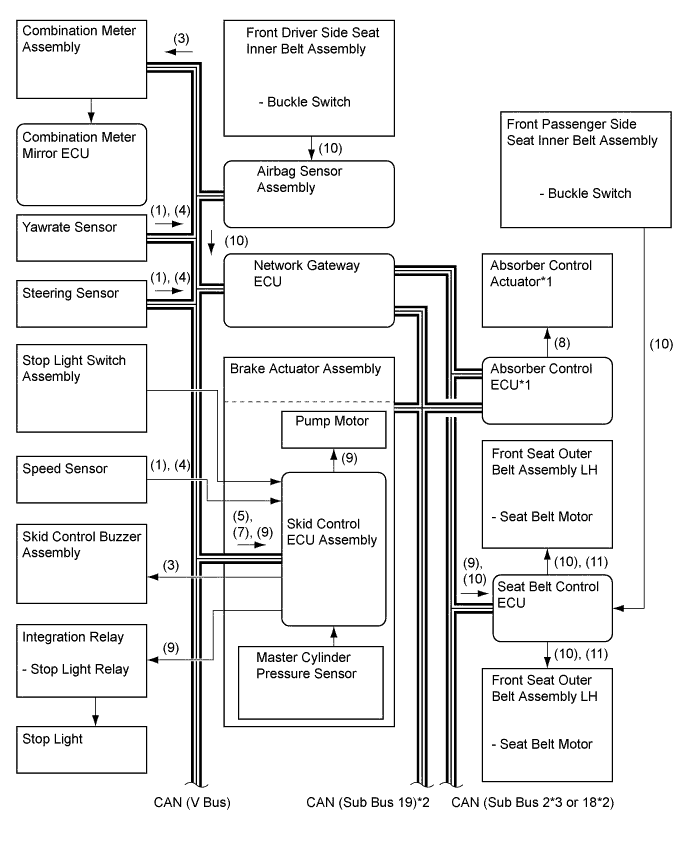
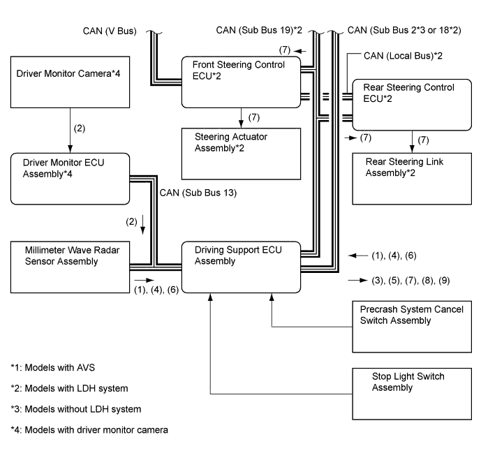
Driver is Facing Forward and Eyelids are Open (Models with Driver Monitor Camera) (1) The driving support ECU assembly determines that the possibility of a collision is high based on the signals received from the millimeter wave radar sensor assembly, steering sensor, speed sensor and yawrate sensor. (2) The driving support ECU assembly transmits a BRAKE! warning display request signal to the combination meter assembly and a skid control buzzer request signal to the skid control ECU assembly. (3) The driving support ECU assembly determines that an unavoidable collision condition exists based on the signals received from the millimeter wave radar sensor assembly, speed sensor, steering sensor and yawrate sensor. (4) The driving support ECU assembly outputs a pre-crash brake assist request signal to the skid control ECU assembly. Upon receiving this signal, the skid control ECU assembly switches the brake assist to the standby condition. At the same time, the driving support ECU assembly outputs a steering assist request signal to the front and rear steering control ECU assembly. Upon receiving this signal, the front and rear steering control ECU switches the Lexus dynamic handling system to the standby condition. (5) The driving support ECU assembly outputs an AVS request signal to the absorber control ECU. Upon receiving this signal, the absorber control ECU controls the absorber control actuators. (6) The driving support ECU assembly outputs a seat belt operation request signal to the seat belt control ECU and a pre-crash brake request signal to the skid control ECU assembly. (7) The seat belt control ECU determines the seat belt motor operation condition based on this signal and the seat belt buckle switch signal, and retracts the slack in the seat belts by operating the seat belt motors. At the same time, the skid control ECU assembly activates the brake actuator assembly as a pre-crash brake control and decelerates the vehicle. (8) If no collision occurs, the seat belts and the brake assist will return to their normal states. 
-
Opening or Closing of Eyelids and Face Direction Determination
-
Models with driver monitor camera, the driver monitor ECU assembly detects the driver who do not facing forward or do not opening the eyelids, then the driving support ECU assembly hasten the warning.
-
After the warning, if the driver's condition has not changed, the driving support ECU assembly activates the warning brake operation.
-
-
-
FUNCTION
-
Warning Messages Displayed in Combination Meter Assembly
-
The combination meter assembly uses the master warning light, PCS warning light, multi buzzer and multi-information display to provide the driver with pre-crash safety system warnings and indications.
-
If the driving support ECU assembly determines that there is a possibility of a collision, it sends a signal to the combination meter assembly. Upon receiving this signal, the combination meter assembly indicates a warning on the multi-information display, master warning light and PCS warning light. Details are indicated below.
-
If the driving support ECU assembly determines that the possibility of a collision is high, it sends a signal to the combination meter assembly. Upon receiving this signal, the combination meter gives a warning using the multi-information display, master warning light and PCS warning light, and sounds the skid control buzzer assembly. Details are indicated below:
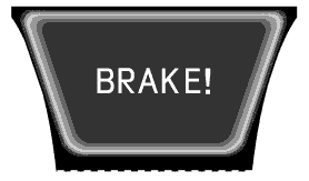
There is a High Possibility of a Collision Headup Display* Multi-information Display Master Warning Light PCS Warning Light Skid Control Buzzer Assembly 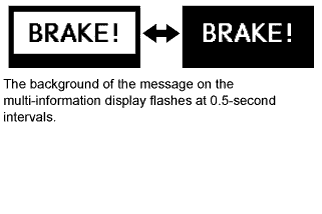
- Flashes Sounds Continuously
-
*: Models with combination meter mirror ECU
-
-
2 types of warning messages are used for the pre-collision system, as described below. The pre-collision system will not operate when these messages appear in the combination meter assembly.
When the Pre-crash Safety System will not Operate Multi-information Display Detail Master Warning Light PCS Warning Light Multi Buzzer DTC 
This message appears when the seat belt control ECU detects a system malfunction. Illuminates Illuminates Sounds Once ○ 
This message appears when the seat belt control ECU determines the following conditions:
-
Dirty front millimeter wave radar sensor
-
Poor weather condition
-
Overheated seat belt control ECU
After these conditions have been resolved, the system will operate normally.
- Flashes - - Tech Tips
○: Repair is required/DTCs are output
-: Repair is not required/DTCs are not output
-
-
-
-
CONSTRUCTION
-
Millimeter Wave Radar Sensor Assembly
-
The millimeter wave radar sensor assembly consists of a millimeter wave radar circuit, signal processing circuit, and CPU.
-
The millimeter wave radar outputs waves when the vehicle speed is above 0 km/h, and not when the vehicle speed is at 0 km/h. The millimeter wave radar uses frequencies in the 76.5 GHz band.
-
The reception antennas receive the millimeter wave radar waves that have been reflected.
-
The signal processing circuit detects the distance, relative speed, and the direction of the object by generating millimeter wave radar waves and calculating the signals received by the reception antennas. Then, it transmits this information to the driving support ECU assembly.
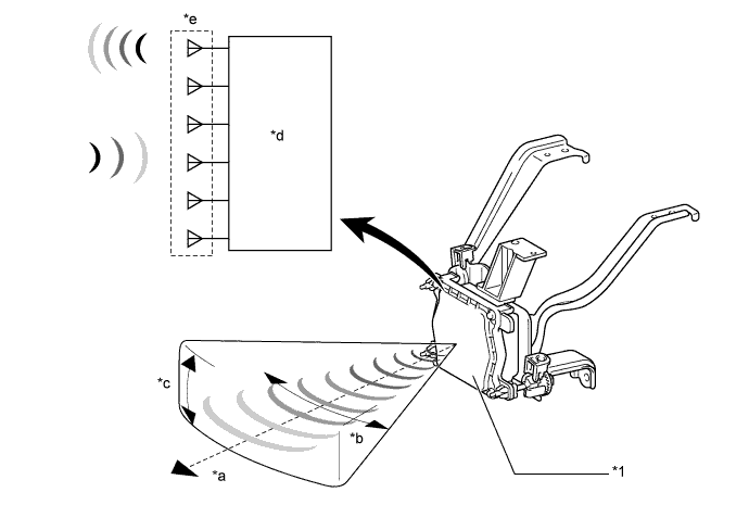
Text in Illustration *1 Millimeter Wave Radar Sensor Assembly - - *a Detection Distance: Approx. 150 m (490 ft.) *b Horizontal Angle: Approx. 20° *c Vertical Angle: Approx. 8° *d Signal Processing Circuit *e Millimeter Wave Radar Circuit - - -
The distance to the object, azimuth, and relative speed are calculated from the information that is provided by the reflection millimeter wave radar as described below.
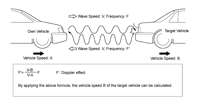
Item Calculation Method Distance Calculated from the length of time that has elapsed from the time the waves of the millimeter wave radar have been emitted, until the waves reflected by the millimeter wave radar are received. The detection distance is approx. 150 m (490 ft.). Azimuth Calculated from the angle of the waves reflected by the millimeter wave radar that have been received. The detection angle has a horizontal angle of approx. 20° and a vertical angle of approx. 8°. Relative Speed Calculated by utilizing the changes (Doppler effect*) that occur in the frequencies of the reflected millimeter wave radar waves. Tech Tips
*: The Doppler effect causes the observer to perceive the radio waves emitted by a moving object to be of higher frequencies as it approaches, and to be of lower frequencies at it recedes.
Tech Tips
An SST is used if radar axis adjustment is needed. For details, refer to the Repair Manual
-
-
Driver Monitor Camera (Models with Driver Monitor Camera)
-
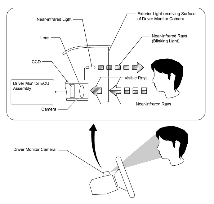
The driver monitor camera, which is mounted on the steering column, monitors the driver's face and eyelids, and transmits image data to the driver monitor ECU assembly.
-
The 2 near-infrared lights that are built into the driver monitor camera illuminate the driver's face and eyelids. Then, the reflected light will consist primarily of near-infrared rays after it passes through the exterior light-receiving surface (which is made of a material that suppresses the transmission of visible rays). The CCD receives the reflected light, thus enabling the monitoring of the driver's face and eyelids even in the dark.
-
The 2 near-infrared lights that are built into the driver monitor camera illuminate the driver's face when the system is turned on.
-
-
Driver Monitor ECU Assembly (Models with Driver Monitor Camera)
-
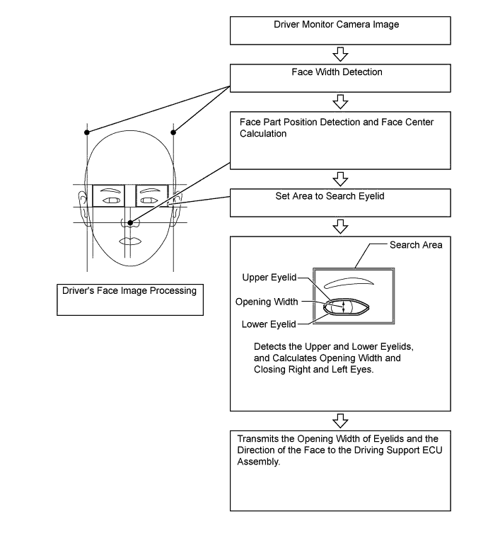
The driver monitor ECU assembly calculates the direction of the driver's face in accordance with the width of the face and the position of the eyes and the mouth, and calculates the open or close condition of the driver's eyelids in accordance with the width of the upper and lower line of eyes, found in the image data received from the driver monitor camera. Then, it transmits a face direction and eyelids open or close condition detection signal to the driving support ECU assembly.
-
-