BRAKE CONTROL SYSTEM DETAILS
-
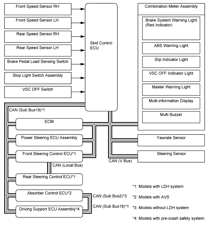
FUNCTION OF MAIN COMPONENTS
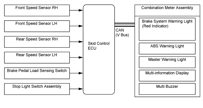
Component Function Combination Meter Assembly Brake System Warning Light (Red Indicator)
-
Illuminates to alert the driver when the skid control ECU detects a malfunction in the EBD.
-
Illuminates to alert the driver when the brake fluid level is low.
ABS Warning Light Illuminates to alert the driver when the skid control ECU detects a malfunction in the ABS. Slip Indicator Light
-
Blinks to inform the driver when the TRC, VSC and hill-start assist control are operational.
-
Illuminates to alert the driver when the skid control ECU detects a malfunction in the TRC, VSC or hill-start assist control.
VSC OFF Indicator Light Illuminates to inform the driver when VSC OFF mode is selected. Master Warning Light Illuminates when the warning message is displayed in the multi-information display. Multi-information Display
-
Displays a information message when TRC OFF mode.
-
Displays a warning message when the skid control ECU detects a malfunction in the ABS or EBD.
Multi Buzzer Sounds intermittently to inform the driver that the hill-start assist control is active. VSC OFF Switch Enables the driver to select "Normal Mode", "TRC OFF Mode", or "VSC OFF Mode". Brake Pedal Load Sensing Switch Detects the brake pedal load. Stop Light Switch Assembly Detects the brake pedal depressing signal. Yawrate Sensor
-
Detects the vehicle's longitudinal and lateral acceleration.
-
Detects the vehicle's yaw rate.
Steering Sensor Detects the direction and angle of the steering wheel. Brake Actuator Assembly
- Master Cylinder Pressure Sensor
- Skid Control ECU
-
Changes the fluid path based on the signals from the skid control ECU during the operation of the brake control system functions, in order to control the fluid pressure applied to the wheel cylinders.
-
Detects the master cylinder pressure.
-
Judges the vehicle driving condition based on the signals from each sensor, and sends the brake control signals to the brake actuator.
Parking Brake ECU Assembly Sends the electric parking brake condition to the skid control ECU. Power Steering ECU Assembly Controls the steering assist torque based on the signals received from the skid control ECU. Front Steering Control ECU (Models with LDH System)
-
Controls the turning angle of the front wheels based on the signals received from the skid control ECU.
-
Calculates the turning angle of the rear wheels and sends it to the rear steering control ECU.
Rear Steering Control ECU (Models with LDH System) Controls the turning angle of the rear wheels based on the signals received from the front steering control ECU. Absorber Control ECU (Models with AVS) Controls the damping force based on the signals received from the skid control ECU. Driving Support ECU Assembly (Models with Pre-crash Safety System) Makes a request for brake control to the skid control ECU. ECM
-
Sends the throttle position signal, accelerator pedal position signal, engine speed signal etc., to the skid control ECU.
-
Controls the engine output based on the signals received from the skid control ECU.
4WD ECU Assembly (AWD Models) Conducts the drive force distribution control based on the signals received from the skid control ECU. -
-
SYSTEM CONTROL
Control Function Anti-lock Brake System (ABS) The ABS helps prevent the wheels from locking when the brakes are applied firmly or when braking on a slippery surface. Electronic Brake Force Distribution (EBD) The EBD utilizes ABS, achieving proper brake force distribution between the front and rear wheels in accordance with the driving conditions. In addition, during braking while cornering, the EBD also controls the brake forces of the right and left wheels, helping maintain vehicle behavior. Brake Assist
-
The primary purpose of brake assist is to provide an auxiliary brake force to assist a driver who cannot generate a large brake force during emergency braking, thus helping ensure the vehicle's braking performance.
-
If the brake booster malfunctions and the skid control ECU judges that the brake pedal force applied by the driver is not sufficient to ensure adequate braking force, brake assist is used to enhance the braking force.
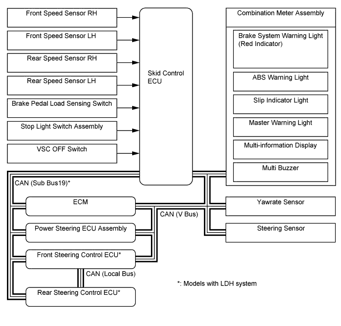
Traction Control (TRC) The TRC helps restrain the slippage of the drive wheels if the driver depresses the accelerator pedal excessively when starting off or while accelerating on a slippery surface. Vehicle Stability Control (VSC) The VSC helps restrain sideways slippage of the vehicle during a strong front wheel skid or strong rear wheel skid, which may occur while cornering. Steering Cooperative Control Effects cooperative control with the power steering ECU assembly, front steering control ECU* and rear steering control ECU* in order to provide steering assist in accordance with the operating conditions of the vehicle. Hill-start Assist Control When starting uphill, this control maintains the brake hydraulic pressure on all 4 wheels, in order to momentarily prevent the vehicle from descending backward.
-
*: Models with LDH system
-
Anti-lock Brake System (ABS)
-
The ABS prevents the wheels from locking during sudden braking or braking on a slippery surface. This provides the proper braking force when the vehicle slips, thus ensuring vehicle stability and excellent braking performance.
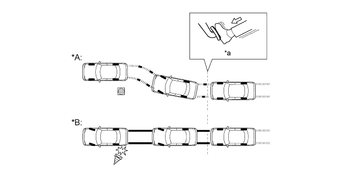
Text in Illustration (Illustration Provides Conceptual Image) *A Models with ABS *B Models without ABS *a Brake Operation - -
-
-
Electronic Brake Force Distribution (EBD)
-
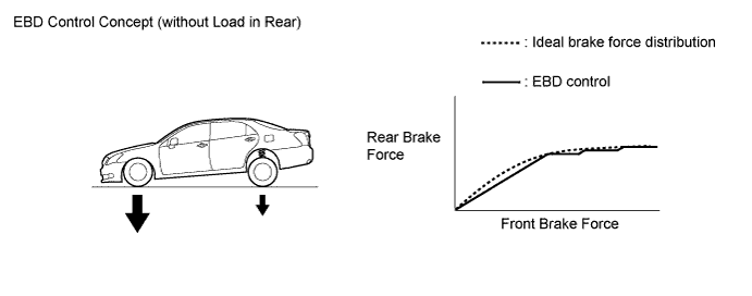
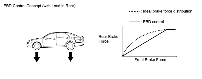
This function controls the brake force that acts on the rear wheels in accordance with the changes in the vehicle conditions such as load factors or deceleration, in order to ensure excellent braking performance.
-
During cornering braking, this function controls the brake force that acts on the left and right wheels in accordance with the vehicle conditions. This ensures vehicle stability and excellent braking performance.

Text in Illustration 
Control Moment 
Brake Force
-
-
Brake Assist
-
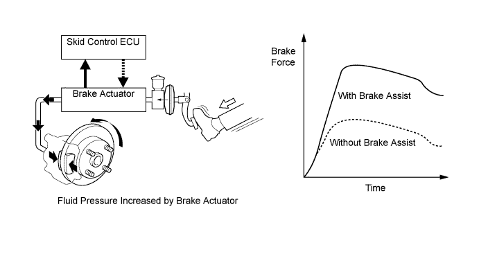
During the brake assist, the skid control ECU calculates the speed and the amount of the brake pedal application based on the signals from the master cylinder pressure sensor and then determines the intention of the driver to make an emergency brake application. If the skid control ECU determines that the driver intends to make an emergency brake application, this function activates the brake actuator to increase the brake fluid pressure, which increases the brake force.
-
-
Traction Control (TRC)
-
The TRC helps prevent the drive wheels from slipping if the driver depresses the accelerator pedal excessively when starting off or accelerating on a slippery surface. Simultaneously with the hydraulic brake control of the drive wheels, the skid control ECU makes a request to the ECM to effect engine output control. This produces the drive force that suits the driving conditions, in order to ensure the proper start-off acceleration.
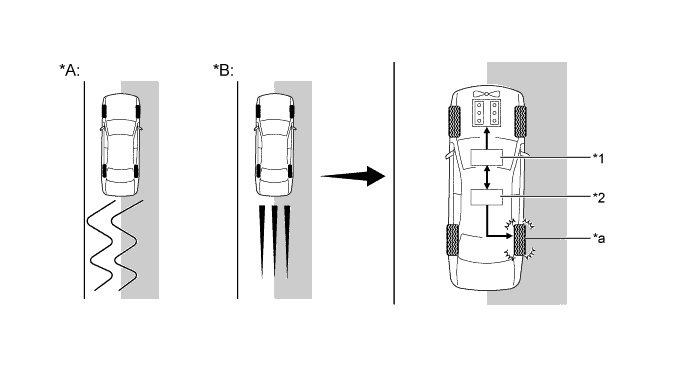
Text in Illustration (Driving on Road with Differing Surface Friction Characteristics) *A Models without TRC *B Models with TRC *1 ECM (Engine Output Control) *2 Brake Actuator Assembly (Hydraulic Brake Control) *a Brake Slipping Drive Wheel - - 
Slippery Surface - -
-
-
Vehicle Stability Control (VSC)
-
The following are 2 examples that can be considered circumstances in which the tires exceed their lateral grip limit. The VSC is designed to help control the vehicle behavior by controlling the engine output and the brakes of each wheel when the vehicle is under one of the conditions indicated below:
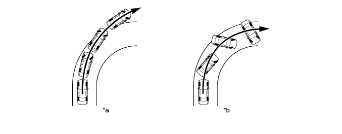
Text in Illustration *a Front Wheel Skid Tendency (Understeer)
- When the front wheels lose grip in relation to the rear wheel
*b Rear Wheel Skid Tendency (Oversteer)
- When the rear wheels lose grip in relation to the front wheels
-
To determine the condition of the vehicle, sensors detect the steering angle, vehicle speed, vehicle yaw rate, and vehicle's lateral acceleration, which are then calculated by the skid control ECU.
-
Whether or not the vehicle is experiencing a front wheel skid is determined by the difference between the target yaw rate and the vehicle's actual yaw rate. When the vehicle's actual yaw rate is smaller than the target yaw rate (which is determined based on the vehicle speed and steering angle) that should be generated when the driver operates the steering wheel, it means the vehicle is making a turn at a greater angle than the target locus of travel. Thus, the skid control ECU determines that there is a large front wheel skid tendency.
Text in Illustration *a Actual Locus of Travel (Actual Yaw Rate) *b Locus of Travel Based on Target Yaw Rate -
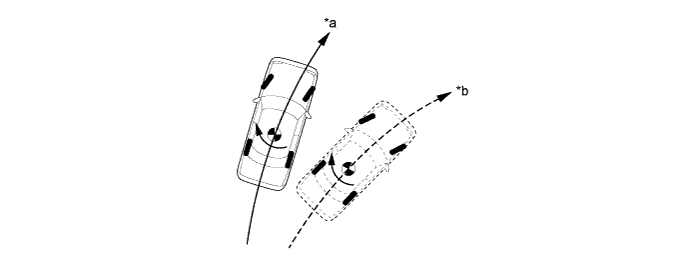
Whether or not the vehicle is experiencing a rear wheel skid is determined by the values of the vehicle's slip angle and the vehicle's slip angular velocity (time-dependent changes in the vehicle's slip angle). When the vehicle's slip angle is large, and the slip angular velocity is also large, the skid control ECU determines that the vehicle has a large rear wheel skid tendency.

Text in Illustration *a Travel Direction of Vehicle's Center of Gravity *b Movement of Vehicle Slip Angle - - -
When the skid control ECU determines that the vehicle is exhibiting a tendency to experience a front wheel skid or a rear wheel skid, it decreases the engine output and applies the brakes of each wheel to control the vehicle's yaw moment. The basic operation of the VSC is described below. However, the control method differs depending on the vehicle's characteristics and driving conditions.
-
When the skid control ECU determines that there is a large front wheel skid tendency, it takes countermeasures in accordance with the extent of that tendency. The skid control ECU controls the engine output and applies the brakes of both rear wheels and the front wheel on the outside of the turn in order to help restrain the front wheel skid tendency.

Text in Illustration Control Moment Brake Force -
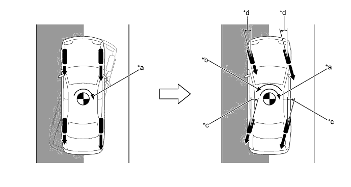
When the skid control ECU determines that there is a large rear wheel skid tendency, it takes countermeasures in accordance with the extent of that tendency. It applies the brakes of the front and rear wheels of the outer circle of the turn, and generates an outward moment of inertia in the vehicle, in order to restrain the rear wheel skid tendency. Along with the reduction in the vehicle speed caused by the braking force, excellent vehicle stability is ensured. In some cases, the skid control ECU applies the brake of the rear wheels, as necessary.

Text in Illustration Control Moment Brake Force
-
-
Steering Cooperative Control
-
Brake Force Control on Roads with High and Low Friction Coefficient
-
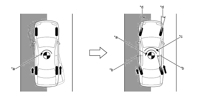
Brake force increases in the high μ (friction coefficient) area of the road and the vehicle attempts to deviate rightward (in the high μ side). Therefore, the front wheels are steered to face the vehicle leftward, thus counteracting the moment generated in the rotating direction. The rear wheels and front wheels are steered in opposite directions, thus controlling the lateral movement of the vehicle.
Text in Illustration (Illustration Provides Conceptual Image) *a Moment Generated due to Left and Right Brake Force Differences *b Control Moment by Steering Control *c Controls Turning Angle of Rear Wheels (Models with LDH System) *d Controls Turning Angle of Front Wheels (Models with LDH System) Brake Force - - Slippery Surface - -
-
-
Acceleration Control on Roads with High and Low Friction Coefficient
-
Drive force increases in the high μ (friction coefficient) area of the road and the vehicle tilts leftward (in the low μ side). Therefore, the front wheels are steered to face the vehicle rightward, thus counteracting the moment generated in the rotating direction. The rear wheels and front wheels are steered in opposite directions, thus controlling the lateral movement of the vehicle.
Text in Illustration (Illustration Provides Conceptual Image) *a Moment Generated due to Left and Right Drive Force Differences *b Controls Turning Angle of Rear Wheels (Models with LDH System) *c Control Moment by Steering Control *d Controls Turning Angle of Front Wheels (Models with LDH System) Drive Force - - Slippery Surface - - Tech Tips
-
On models without LDH system, VDIM controls the vehicle to maintain a straight driving line.
-
On models with LDH system, high brake force and drive force can be maintained during control due to increased vehicle stability.
-
-
-
Oversteering Control
-
When the rear wheels are slipping laterally, both normal brake control and drive force control and steering control of the front and rear wheels stabilize the vehicle movement. Stabilization moment is generated not only by brake force and drive force but also by steering control, thus stabilizing the vehicle without causing an extra speed reduction feel.
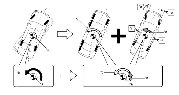
Text in Illustration (Illustration Provides Conceptual Image) *a Rear Wheel Skid Moment *b Moment Necessary to Suppress Oversteering *c Control Moment by Brake Control and Drive Force Control *d Control Moment by Steering Control *e Front Wheel Turning Angle Control (Models with LDH System) *f Rear Wheel Turning Angle Control (Models with LDH System)
-
-
Understeering Control
-
Brake force and drive force are controlled to generate force in the same direction as the turning direction, thus suppressing excessive lateral slippage. In addition, VGRS steering gear ratio is changed to suppress oversteer in the front wheels. Torque assist is applied in the return direction of the steering wheel, thus prompting the driver's steering operation.
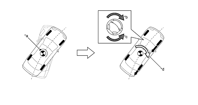
Text in Illustration (Illustration Provides Conceptual Image) *a Front Wheel Skid Moment *b Steering Torque Assist Direction to Inform of Front Wheel Skid *c Steering Torque Assist Direction to Prevent Excessive Turning *d Control Moment by Brake Control and Drive Force Control
-
-
-
Hill-start Assist Control
-
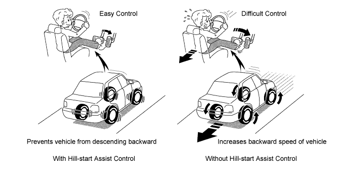
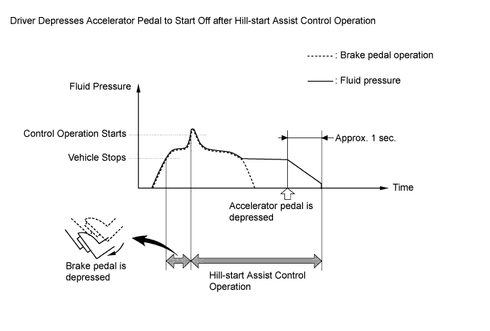
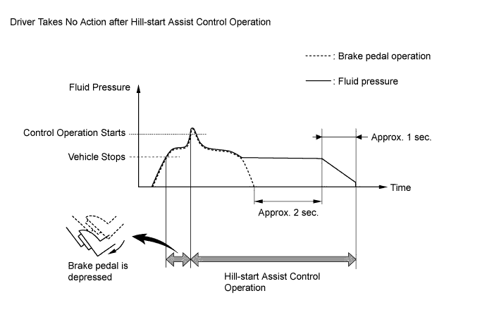
When the vehicle starts off on a steep or slippery hill, it may start to descend backward while the driver switches from the brake pedal to the accelerator pedal, thus making it difficult for the vehicle to start off. To prevent this from occurring, the hill-start assist control temporarily (approximately 2 seconds at the maximum) applies the brakes to the 4 wheels in order to prevent the vehicle from descending backward.
-
Without the hill-start assist control, the driver must quickly and precisely switch from the brake pedal to the accelerator pedal. With the hill-start assist control, however, the driver can start off easily and operate the pedal in a relaxed manner, because the hill-start assist control prevents the vehicle from descending backward.
-
If all of the following conditions have been met, and if the driver depresses the brake pedal further while the vehicle is stopped, the system starts the hill-start assist control:
-
The shift lever is in any position other than P.
-
The accelerator pedal is not depressed.
-
The vehicle is at a standstill.
-
The parking brake is unlocked.
-
-
-
-
FUNCTION
-
VSC OFF Switch
-
The operation of the VSC and TRC functions can be stopped by the VSC OFF switch. While the vehicle is running off the shoulder of the road or running on a dirt road, the engine output control is stopped to maintain drive torque.
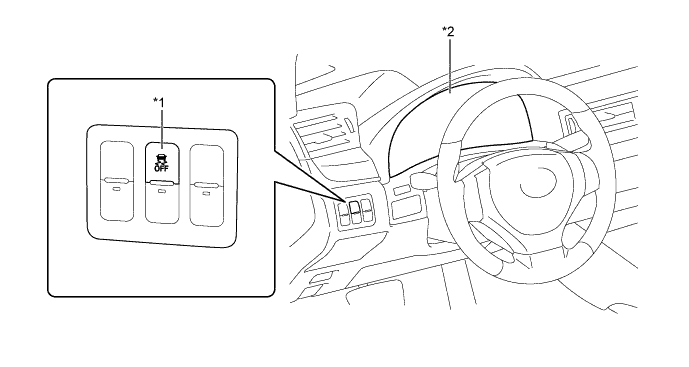
Text in Illustration *1 VSC OFF Switch *2 Combination Meter Assembly -
The VSC OFF switch can select 3 modes (Normal mode, TRC OFF mode, and VSC OFF mode).
-
Briefly pressing the VSC OFF switch in Normal mode selects TRC OFF mode.
-
Pressing and holding the VSC OFF switch for 3 seconds or more with the vehicle stopped selects VSC OFF mode, disabling the TRC and VSC functions.
-
Briefly pressing the VSC OFF switch in TRC OFF mode or VSC OFF mode or turning the engine switch off returns to the Normal mode.
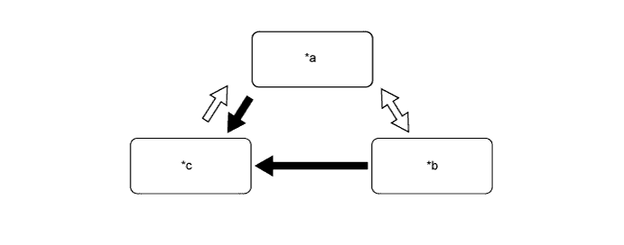
Text in Illustration *a Normal Mode *b TRC OFF Mode *c VSC OFF Mode - - VSC OFF Switch Operation (Press and Hold for 3 Seconds or More) VSC OFF Switch Operation (Brief) -
The operations of the brake control functions in each mode are as follows:
Mode Brake Control Function Combination Meter TRC VSC VSC OFF Indicator Light Multi-information Display Normal Mode Controllable Controllable - - TRC OFF Mode Not Controllable Controllable - Display VSC OFF Mode Not Controllable Not Controllable* Illuminates - Tech Tips
*: The control is effected during braking or while the yaw rate is large.
-
-
-
CONSTRUCTION
-
Steering Sensor
-
The steering sensor detects the steering direction and angle.
-
2 pairs of magnetoresistive elements are provided in the actuator to detect rotation of the magnet built into the detection gear. The actuator detects magnetic resistance changes during detection gear rotation as the rotation of the steering wheel.
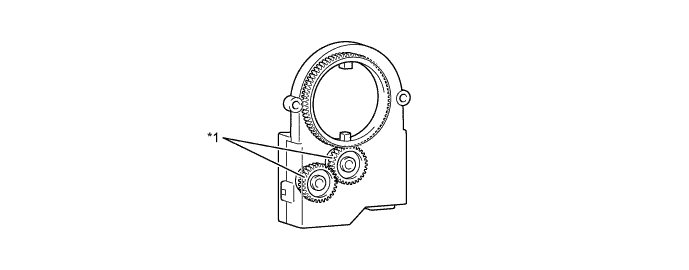
Text in Illustration *1 Detection Gear - -
-
-
Yawrate Sensor
-
The yawrate sensor and the deceleration sensor are integrated together for compactness and located in the lower portion of the center console.
-
The yawrate sensor detects capacitance changes caused by the vehicle's vertical axis rotation as a rotation angle speed.
-
The deceleration sensor detects capacitance changes between the movable electrode and fixed electrode as the vehicle's deceleration. 2 deceleration sensors, installed at 45-degree angles in the vehicle's front and rear direction, are used to enable the detection of the whole vehicle's deceleration in the horizontal direction.

-
-
Speed Sensor
-
An active type speed sensor is used. This sensor contains a sensor IC, which consists of 2 Magnetic Resistance Elements (MREs).
-
The magnet type rotor, which consists of N and S poles that are arranged in a circle, is integrated with the hub bearing inner race.
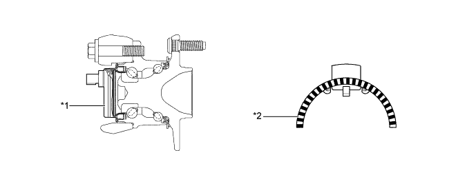
Text in Illustration (2WD Models) *1 Front Speed Sensor *2 Sensor Rotor 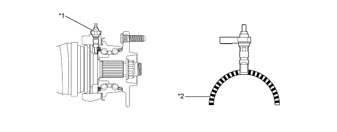
Text in Illustration (AWD Models) *1 Front Speed Sensor *2 Sensor Rotor 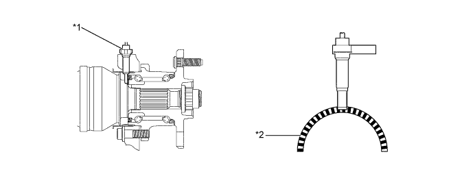
Text in Illustration *1 Rear Speed Sensor *2 Sensor Rotor
-
-
Brake Actuator Assembly
-
The brake actuator assembly consists of the brake actuator portion and skid control ECU.
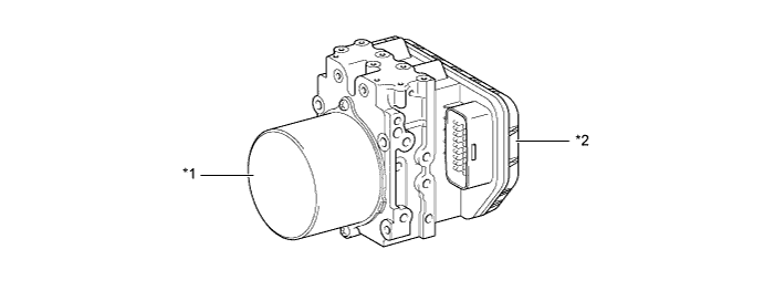
Text in Illustration *1 Brake Actuator Portion *2 Skid Control ECU -
The actuator portion consists of 2 master cylinder cut solenoid valves, 4 pressure holding solenoid valves, 4 pressure reduction solenoid valves, 2 pumps, 2 reservoirs, and a master cylinder pressure sensor.
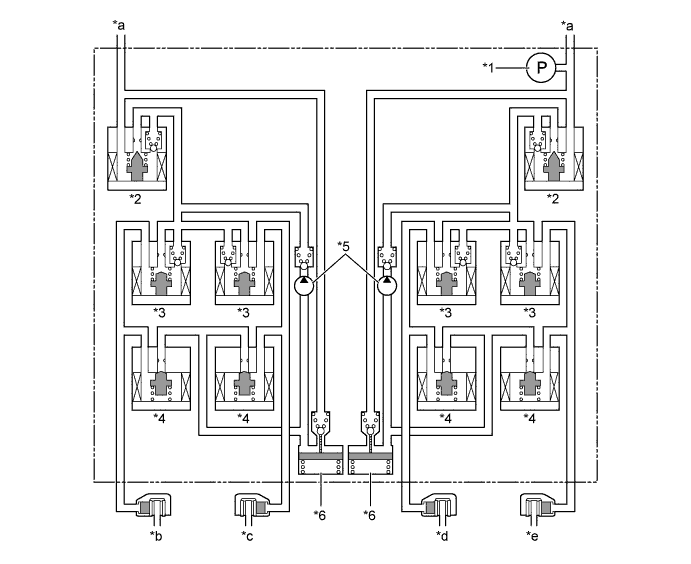
Text in Illustration *1 Master Cylinder Pressure Sensor *2 Master Cylinder Cut Solenoid Valve *3 Pressure Holding Solenoid Valve *4 Pressure Reduction Solenoid Valve *5 Pump *6 Reservoir *a From Master Cylinder *b Front Brake RH *c Front Brake LH *d Rear Brake RH *e Rear Brake LH - -
-
-
-
OPERATION
-
ABS and EBD
-
Based on the signals received from the 4 speed sensors, the skid control ECU calculates the speed of each wheel, and checks the wheel slipping conditions. In accordance with the slipping condition, the skid control ECU controls each solenoid valve in the brake actuator in order to adjust the fluid pressure of each wheel cylinder in the following 3 modes: pressure increase, pressure holding, and pressure reduction modes.
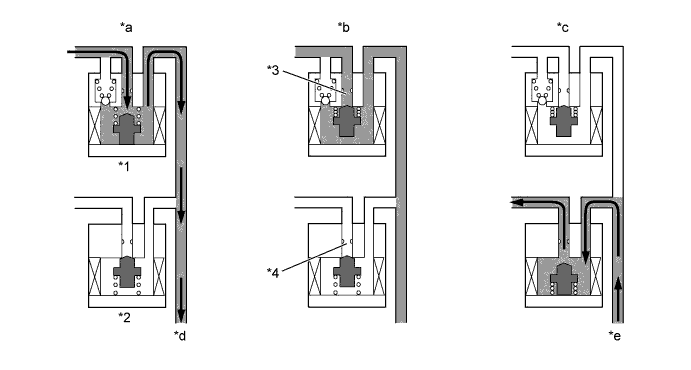
Text in Illustration *1 Pressure Holding Solenoid Valve *2 Pressure Reduction Solenoid Valve *3 Port A *4 Port B *a Pressure Increase Mode *b Pressure Holding Mode *c Pressure Reduction Mode *d To Wheel Cylinder *e From Wheel Cylinder - - Brake Actuator Operation in ABS and EBD Pressure Mode Increase Mode Holding Mode Reduction Mode Pressure Holding Solenoid Valve (Port A) Off (Open) On (Closed) ← Pressure Reduction Solenoid Valve (Port B) Off (Closed) ← On (Open) Wheel Cylinder Pressure Increases Holds Reduces
-
-
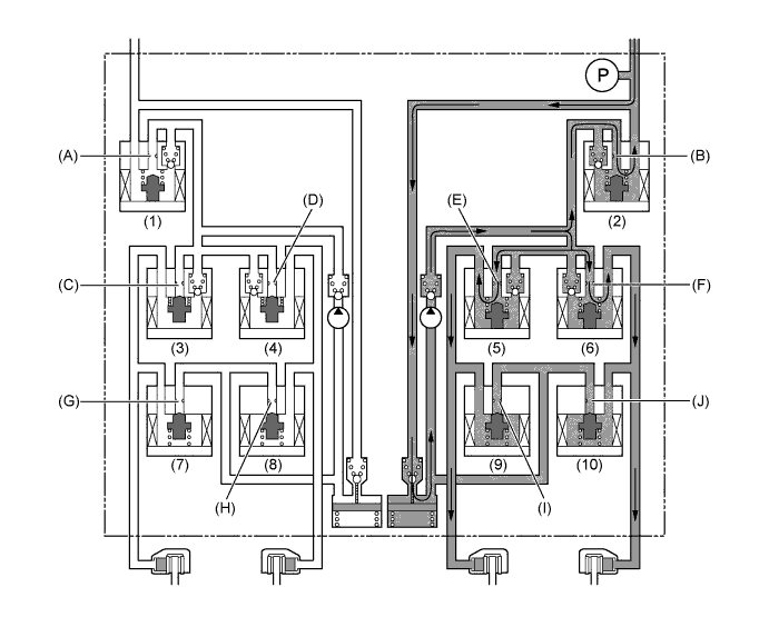
Brake Assist
-
In the event of emergency braking, the skid control ECU determines the driver's intention based on the speed of the pressure increase in the master cylinder determined by the master cylinder pressure sensor signal. If the skid control ECU judges the need for additional brake assist, pressure is generated by the pump in the brake actuator and directed to the wheel cylinder to apply a large amount of fluid pressure.
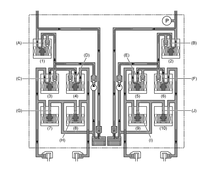
Brake Actuator Operation in Brake Assist Item Brake Assist Not Activated Brake Assist Activated Pump Off On Master Cylinder Cut Solenoid Valve (1) Port (A) Off (Open) On* (2) Port (B) Off (Open) On* Pressure Holding Solenoid Valve (3) Port (C) Off (Open) ← (4) Port (D) Off (Open) ← (5) Port (E) Off (Open) ← (6) Port (F) Off (Open) ← Pressure Reduction Solenoid Valve (7) Port (G) Off (Closed) ← (8) Port (H) Off (Closed) ← (9) Port (I) Off (Closed) ← (10) Port (J) Off (Closed) ← Tech Tips
*: The solenoid valve switches the hydraulic pressure between "open" and "closed" in accordance with the operating conditions by adjusting continually.
-
-
TRC
-
The fluid pressure generated by the pump is regulated by the master cylinder cut solenoid valve to the required pressure. Thus, the wheel cylinders of the drive wheels are controlled in the following 3 modes: pressure increase, pressure holding, and pressure reduction modes to control the slippage of the drive wheels. The pressure holding solenoid valve and the pressure reduction solenoid valve are turned on or off in accordance with the ABS and EBD operation patterns.
Brake Actuator Operation in TRC Item TRC Operation Not Activated Pressure Increase Mode Pressure Holding Mode Pressure Reduction Mode Pump Off On ← ← Master Cylinder Cut Solenoid Valve (1) Port (A) Off (Open) ← ← ← (2) Port (B) Off (Open) On* ← ← Front Brake Pressure Holding Solenoid Valve (3) Port (C) Off (Open) On (Closed) ← ← (4) Port (D) Off (Open) On (Closed) ← ← Pressure Reduction Solenoid Valve (7) Port (G) Off (Closed) ← ← ← (8) Port (H) Off (Closed) ← ← ← Wheel Cylinder Pressure Right - - - - Left - - - - Rear Brake Pressure Reduction Solenoid Valve (5) Port (E) Off (Open) On* On (Closed) ← (6) Port (F) Off (Open) On* On (Closed) ← Pressure Reduction Solenoid Valve (9) Port (I) Off (Closed) ← ← On (Open) (10) Port (J) Off (Closed) ← ← On (Open) Wheel Cylinder Pressure Right - Increases Holds Reduces Left - Increases Holds Reduces Tech Tips
*: The solenoid valve switches the hydraulic pressure between "open" and "closed" in accordance with the operating conditions by adjusting continually.
-
-
VSC
-
The VSC, by way of solenoid valves, controls the fluid pressure generated by the pump and applies it to the brake wheel cylinder of each wheel in the following 3 modes: pressure increase, pressure holding, and pressure reduction modes. As a result, the tendency to front wheel skid or rear wheel skid is controlled.
-
In the front wheel skid restraining control, the brakes of the front wheel on the outer circle of the turn and the rear wheels are applied. Also, depending on whether the brake is on or off and also depending on the condition of the vehicle, there are circumstances in which the brake might not be applied to the wheels even if the wheel is targeted for braking. The following diagram shows the hydraulic circuit in the pressure increase mode, as it controls the front wheel skid condition while the vehicle is making a right turn. In other operating modes, the pressure holding valve and the pressure reduction valve are turned on or off in accordance with the ABS and EBD operation patterns.
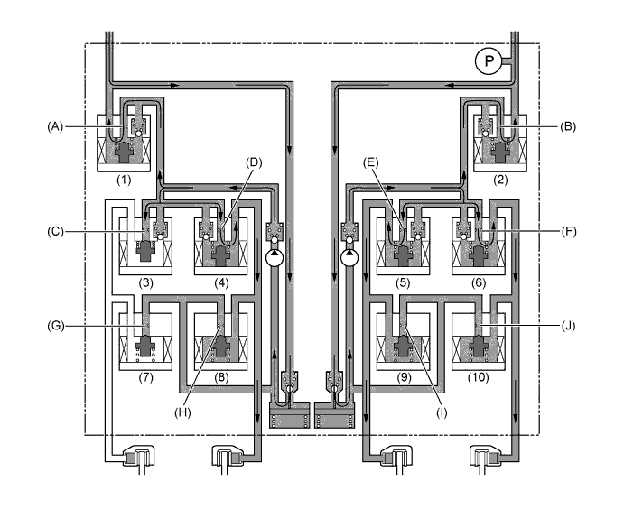
Brake Actuator Operation in VSC (Front Wheel Skid Restraining) Item VSC Operation Not Activated Pressure Increase Mode Pressure Holding Mode Pressure Reduction Mode Pump Off On ← ← Master Cylinder Cut Solenoid Valve (1) Port (A) Off (Open) On* ← ← (2) Port (B) Off (Open) On* ← ← Front Brake Pressure Holding Solenoid Valve (3) Port (C) Off (Open) On (Closed) ← ← (4) Port (D) Off (Open) On* On (Closed) ← Pressure Reduction Solenoid Valve (7) Port (G) Off (Closed) ← ← ← (8) Port (H) Off (Closed) ← ← On (Open) Wheel Cylinder Pressure Right - - - - Left - Increases Holds Reduces Rear Brake Pressure Reduction Solenoid Valve (5) Port (E) Off (Open) On* On (Closed) ← (6) Port (F) Off (Open) On* On (Closed) ← Pressure Reduction Solenoid Valve (9) Port (I) Off (Closed) ← ← On (Open) (10) Port (J) Off (Closed) ← ← On (Open) Wheel Cylinder Pressure Right - Increases Holds Reduces Left - Increases Holds Reduces Tech Tips
*: The solenoid valve switches the hydraulic pressure between "open" and "closed" in accordance with the operating conditions by adjusting continually.
-
During the rear wheel skid restraining control, the brakes of the front and rear wheels on the outer circle of the turn are applied. Also, depending on whether the brake is on or off and also depending on the condition of the vehicle, there are circumstances in which the brake might not be applied to the wheels even if the wheel is targeted for braking. The following diagram shows the hydraulic circuit in the pressure increase mode, as it controls the rear wheel skid condition while the vehicle is making a right turn. In other operating modes, the pressure holding valve and the pressure reduction valve are turned on or off in accordance with the ABS and EBD operation patterns.
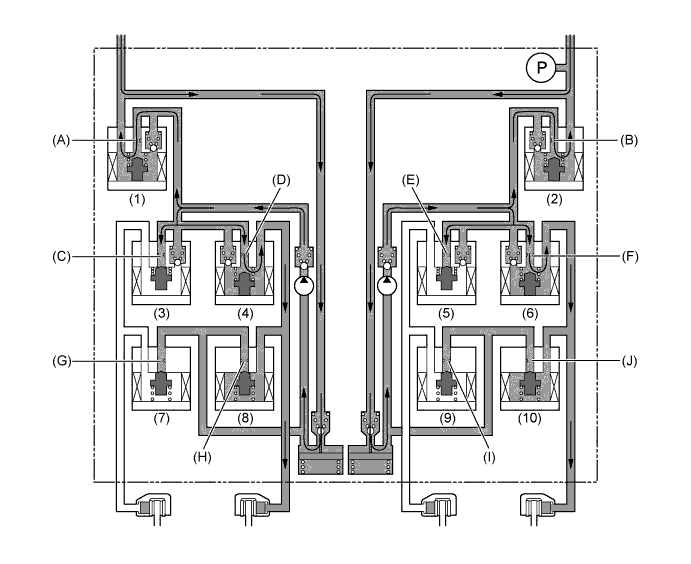
Brake Actuator Operation in VSC (Rear Wheel Skid Restraining) Item VSC Operation Not Activated Pressure Increase Mode Pressure Holding Mode Pressure Reduction Mode Pump Off On ← ← Master Cylinder Cut Solenoid Valve (1) Port (A) Off (Open) On* ← ← (2) Port (B) Off (Open) On* ← ← Front Brake Pressure Holding Solenoid Valve (3) Port (C) Off (Open) On (Closed) ← ← (4) Port (D) Off (Open) On* On (Closed) ← Pressure Reduction Solenoid Valve (7) Port (G) Off (Closed) ← ← ← (8) Port (H) Off (Closed) ← ← On (Open) Wheel Cylinder Pressure Right - - - - Left - Increases Holds Reduces Rear Brake Pressure Reduction Solenoid Valve (5) Port (E) Off (Open) On (Closed) ← ← (6) Port (F) Off (Open) On* On (Closed) ← Pressure Reduction Solenoid Valve (9) Port (I) Off (Closed) ← ← ← (10) Port (J) Off (Closed) ← ← On (Open) Wheel Cylinder Pressure Right - - - - Left - Increases Holds Reduces Tech Tips
*: The solenoid valve switches the hydraulic pressure between "open" and "closed" in accordance with the operating conditions by adjusting continually.
-
-
Steering Cooperative Control
-
The operation of the solenoid valves under the steering cooperative control is the same as the TRC or VSC operation.
-
-
Hill-start Assist Control
-
The skid control ECU determines the starting of the hill-start assist control operation in accordance with information provided by various sensors, switches, and the ECM. At this time, the skid control ECU controls the fluid pressure and applies it by way of the solenoid valves to the brake wheel cylinder of each wheel in the following 2 modes: pressure reduction and pressure holding modes.
-
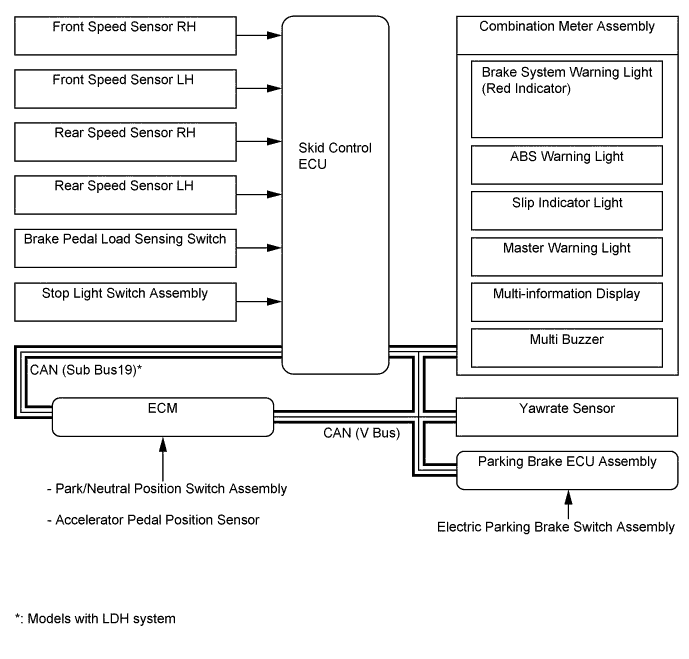
The skid control ECU computes that the vehicle is in a state in which the hill-start assist control can start operating in accordance with the signals provided by the speed sensors, yawrate sensor, park/neutral position switch assembly, stop light switch assembly, accelerator pedal position sensor, and electric parking brake switch assembly. In this state, if the driver depresses the brake pedal further, causing the master cylinder pressure sensor signal to be input into the skid control ECU, the skid control ECU starts the hill-start assist control operation.
-
When hill-start assist control operation starts, the multi buzzer in the combination meter assembly will sound once.
-
During hill-start assist control operation, the slip indicator light blinks and the stop light is illuminated.
-
If a signal indicating one of the conditions listed below has been input into the skid control ECU, the skid control ECU turns off the slip indicator light, sounds the multi buzzer in the combination meter assembly twice, and cancels the hill-start assist control operation.
-
The driver takes no action for 2 seconds or longer after the hill-start assist control operation has started.
-
The driver has moved the shift lever to P.
-
The driver has depressed the accelerator pedal (this will not cause the buzzer to sound).
-
The driver has operated the electric parking brake switch assembly.
-
The driver has depressed the brake pedal.

Brake Actuator Operation in Hill-start Assist Control Item Hill-start Assist Control Operation Not Activated Pressure Holding Mode Pressure Reduction Mode Pump Off On ← Master Cylinder Cut Solenoid Valve (1) Port (A) Off (Open) On* ← (2) Port (B) Off (Open) On* ← Front Brake Pressure Holding Solenoid Valve (3) Port (C) Off (Open) ← ← (4) Port (D) Off (Open) ← ← Pressure Reduction Solenoid Valve (7) Port (G) Off (Closed) ← ← (8) Port (H) Off (Closed) ← ← Wheel Cylinder Pressure Right - Holds Reduces Left - Holds Reduces Rear Brake Pressure Reduction Solenoid Valve (5) Port (E) Off (Open) ← ← (6) Port (F) Off (Open) ← ← Pressure Reduction Solenoid Valve (9) Port (I) Off (Closed) ← ← (10) Port (J) Off (Closed) ← ← Wheel Cylinder Pressure Right - Holds Reduces Left - Holds Reduces Tech Tips
*: The solenoid valve switches the hydraulic pressure between "open" and "closed" in accordance with the operating conditions by adjusting continually.
-
-
-
-
FAIL-SAFE
-
If a failure occurs in the skid control ECU, sensors, or brake actuator, the system continues effecting brake control by excluding the failed area and using only the areas that are operating normally.
-
-
DIAGNOSIS
-
If the skid control ECU detects a malfunction in the brake control system, the warning lights or indicator light illuminate. At the same time, a Diagnostic Trouble Code (DTC) is stored in the memory of the skid control ECU.
-
This system has a sensor signal check (test mode) function.
-
For details of DTC and check function, refer to the Repair Manual.
-