ADAPTIVE VARIABLE SUSPENSION SYSTEM DETAILS
-
FUNCTION OF MAIN COMPONENTS
Component Function Absorber Control Actuator Changes the damping force of the shock absorber assembly. Acceleration Sensor Detects the vertical acceleration rate of the body. Yawrate Sensor Detects the vehicle's longitudinal and lateral acceleration and deceleration. Steering Sensor Detects the steering direction and the angle of the steering wheel. Speed Sensor Detects the vehicle speed. Stop Light Switch Assembly Detects the brake pedal depressing signal. Combination Switch Assembly
- Drive Mode Select
Switches the driving mode (NORMAL mode, SPORT S mode or SPORT S+ mode). Absorber Control ECU (with Built-in Front Acceleration Sensor)
-
Estimates the condition of the vehicle in accordance with the signals provided by the sensors and switches, and outputs control signals to the absorber control actuators.
-
Detects the vertical acceleration rate of the body.
ECM
-
Sends the engine speed signal and the drive torque signal to the absorber control ECU.
-
Sends information of drive mode selected through a drive mode select operation to the absorber control ECU.
Skid Control ECU
-
Sends the vehicle speed signal to the absorber control ECU.
-
Sends the brake pedal depressing signal to the absorber control ECU.
-
Makes a request for damping force control to the absorber control ECU.
Front Steering Control ECU*1 Sends the turning angle signal of the front wheels to the absorber control ECU. Driving Support ECU Assembly*2 Makes a request for damping force control to the absorber control ECU. Combination Meter Assembly
- Multi-information Display
Displays the selected condition of the drive mode select.
-
*1: Models with LDH system
-
*2: Models with pre-crash safety system
-
-
SYSTEM CONTROL
-
The absorber control ECU receives signals from the sensors and switches to control the absorber control actuators. The ECU uses these signals to optimally control the damping force in accordance with the driving conditions and road conditions.
-
The AVS effects the following controls:
Control Outline Roll Posture Control Regulates the damping force to reduce the phase difference between the vehicle roll and pitch angles during steering, thus providing smooth superior maneuverability. Repercussion Control (Non-linear H∞ Control) Smoothly changes the damping force to a target value in accordance with the changes in the road surface or driving conditions. In this way, excellent ride comfort is achieved while ensuring a high level of vibration damping performance. Vehicle Speed Sensing Control Controls damping force in accordance with vehicle speed, thus aiming for both riding comfort at a low speed and superior stability and controllability at a high speed. Anti-dive Control Makes the damping force firmer to restrain the body dive during braking, thus ensuring excellent stability and controllability. Anti-squat Control Makes the damping force firmer during acceleration to minimize the changes in the vehicle body posture. Roughness Sensing Control Controls the shock absorber assemblies so that their damping force will not increase, when the road surface condition does not require a damping force. Unsprung Damping Control Controls so that the damping force will not decrease below a certain level, if unsprung resonance is detected in order to reduce the unsprung resonance. VSC Operation Control Changes the damping force to control the vehicle posture during VSC operation (front or rear skid). Pre-crash Safety System Operation Control* Switches damping force to the hard side in accordance with damping force control request signals from the driving support ECU assembly, and suppresses dive during braking. Damping Mode Selection The drive mode select enables the driver to select a desired damping force from the 2 modes.
-
*: Models with pre-crash safety system
-
-
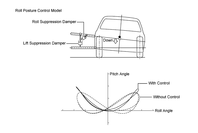
Roll Posture Control
-
In accordance with the steering sensor and yawrate sensor (deceleration sensor signal), the damping force of each wheel is controlled to optimize the vehicle posture condition while turning.
-
Using a roll posture control model, in which absorbers (for roll suppression and lift suppression) are located on the hypothetical inside turning point to control movement in 2 directions, damping force on the inside and outside turning sides is controlled with each of the 4 wheels independent. As a result, vehicle posture when turning is optimized, and groundholding performance is ensured.
-
Damping force is controlled to reduce the phase difference between the roll angle and pitch angle, thus achieving a vehicle posture compatible to the sensitivity of a human as well as comfortable steering.
-
-
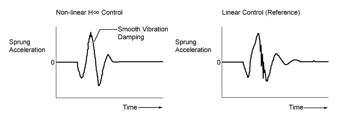
Repercussion Control (Non-linear H∞ Control)
-
In accordance with an acceleration sensor signal, the absorber control ECU detects vehicle vibrations (in the heave, roll and pitch directions) and controls the damping force of each of the 4 wheels using non-linear H∞ control logic. Therefore, vehicle repercussion is naturally and smoothly controlled, thus ensuring riding comfort.
-
-
Damping Mode Selection
-
Drive modes (NORMAL, SPORT S and SPORT S+) can be selected by a driving mode select operation.
-
In NORMAL, ECO or SPORT S mode, riding comfort is prioritized by damping force control which reacts to driving operation and road surface conditions, and control specification ensures that operating performance and stability are also achieved.
-
Compared to NORMAL, ECO or SPORT S mode, SPORT S+ mode utilizes a high damping force region under damping force control, thus achieving control specification to enhance operating performance and stability further.
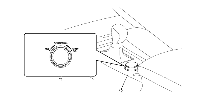
Text in Illustration *1 Drive Mode Select *2 Combination Switch Assembly 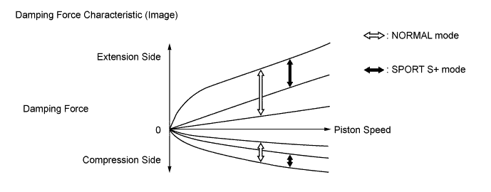
-
-
-
CONSTRUCTION
-
Absorber Control Actuator
-
The absorber control actuator uses a step motor that switches in 9 steps to effect minute changes in the damping force.
-
The step motor consists of 2 sets of stators and coils.
-
To control the damping force, the step motor causes the magnetic rotor, which is directly coupled to the shock absorber control rod, to make small rotational movements in accordance with the signals received from the absorber control ECU.
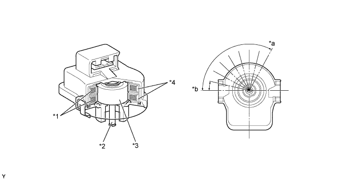
Text in Illustration *1 Coil *2 Output Shaft *3 Magnetic Rotor *4 Stator *a Soft *b Hard
-
-
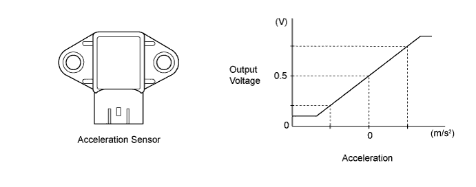
Acceleration Sensor
-
The acceleration sensor detects the vertical movement of the body.
-
3 acceleration sensors are provided. One of them is integrated in the absorber control ECU. The acceleration sensors independently detect the vertical acceleration rate.
-
-
Steering Sensor
-
The steering sensor detects the steering direction and angle.
-
2 pairs of magnetoresistive elements are provided in the actuator to detect rotation of the magnet built into the detection gear. The actuator detects magnetic resistance changes during detection gear rotation as the rotation of the steering wheel.
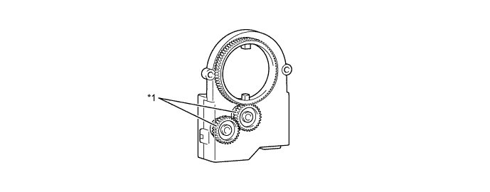
Text in Illustration *1 Detection Gear - -
-
-
Yawrate Sensor
-
The yawrate sensor and the deceleration sensor are integrated together for compactness and located in the lower portion of the center console.
-
The yawrate sensor detects capacitance changes caused by the vehicle's vertical axis rotation as a rotation angle speed.
-
The deceleration sensor detects capacitance changes between the movable electrode and fixed electrode as the vehicle's deceleration. 2 deceleration sensors, installed at 45-degree angles in the vehicle's front and rear direction, are used to enable the detection of the whole vehicle's deceleration in the horizontal direction.

-
-
-
FAIL-SAFE
-
If a malfunction occurs in the AVS, the absorber control ECU prohibits the damping force control.
-
-
DIAGNOSIS
-
The absorber control ECU will also store a Diagnostic Trouble Code (DTC). The DTC can be accessed through the use of a Global Tech Stream (GTS). For details, refer to the Repair Manual.
-