FOUR WHEEL DRIVE CONTROL SYSTEM DETAILS
-
FUNCTION OF MAIN COMPONENTS
Component Function Transfer Control Solenoid Assembly Controls the hydraulic pressure of the center differential limiting clutch in accordance with the signals from the 4WD ECU assembly. Speed Sensors Detect the wheel speed of each 4 wheels. Throttle Position Sensor Detects the opening angle of the throttle valve. Steering Sensor Detects the steering angle of the steering wheel. Park/Neutral Position Switch Assembly Detects the P position. Stop Light Switch Assembly Detects the brake pedal depressing condition. 4WD ECU assembly Detects the signals provided by various sensors, switches and ECUs, actuates the linear solenoid, and controls the AWD control system. Skid Control ECU Detects the signals from the each sensor and outputs them to the 4WD ECU assembly. ECM Sends the throttle valve angle signal and shift position signal to the 4WD ECU assembly. Combination Meter Assembly Slip Indicator Light Informs the driver of a slippery road surface. Master Warning Light Illuminates to alert the driver when the 4WD ECU assembly detects a malfunction in the AWD control system. Multi-information Display Displays a warning to the driver when the AWD control system malfunctions. -
SYSTEM CONTROL
-
The AWD control system has the following controls:
Control Features Vehicle Start-up and Low-speed Turn Control
-
This controls the amount of sideway sliding that occurs at the rear of vehicles when accelerating from a stop to improve acceleration and hill climbing capacity.
-
This prevents tight corner braking during a low-speed turn.
Slip Control at Vehicle Start-up This helps prevent the vehicle from sliding sideways, to accelerate from a stop with the steering wheel turned and ensures a stable start-up and steerability. Slip Control This ensures high turning performance and stability not affected by road surface conditions during mid and high speed running. Acceleration Control This controls straight-line running when accelerating during medium and high speed running to ensure straight-line capacity and stability of the vehicle. -
-
Vehicle Start-up and Low-speed Turn Control
-
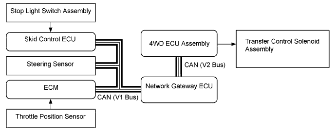
The 4WD ECU assembly controls the transfer control solenoid assembly based on signals from the throttle position sensor, stop light switch assembly and steering angle sensor. The solenoid controls the hydraulic pressure applied to the center differential limiting clutch. Thus, vehicle start-up and low-speed turn control will be performed.
-
The 4WD ECU assembly controls the center differential that is coupled directly before starting the vehicle in order to prevent slipping at vehicle start-up or during acceleration on a grade or a low friction road.
-
The 4WD ECU assembly decreases the hydraulic pressure applied to the center differential limiting clutch during a low-speed turn based on the steering angle to prevent tight corner braking.
-
-
Slip Control at Vehicle Start-up
-
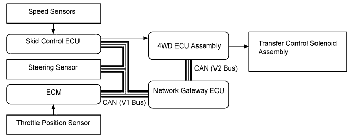
The 4WD ECU assembly controls the transfer control solenoid assembly based on signals from the throttle position sensor, steering angle sensor and 4 speed sensors. The solenoid controls the hydraulic pressure applied to the center differential limiting clutch. Thus, slip control at vehicle start-up will be performed.
-
If the vehicle starts moving with the steering wheel turned, the hydraulic pressure applied to the center differential limiting clutch is decreased by low-speed turn control. An excessive driving force may be applied to the rear wheels on a low friction road, causing the vehicle rear to move sideways. To prevent this, the 4WD ECU assembly detects differences between the front wheel speed and the rear wheel speed based on signals from the 4 speed sensors to directly couple the center differential immediately.
-
-
Slip Control
-
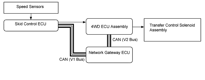
The 4WD ECU assembly controls the transfer control solenoid assembly based on signals from the 4 speed sensors. The solenoid controls the hydraulic pressure applied to the center differential limiting clutch. Thus, slip control will be performed.
-
The 4WD ECU assembly detects differences between the front wheel speed and the rear wheel speed while driving at a medium or high speed based on signals from the 4 speed sensors. Then, the 4WD ECU assembly calculates the hydraulic pressure based on the difference in the wheel speeds and the vehicle speed and continuously applies the appropriate hydraulic pressure to the center differential limiting clutch, which stabilizes the vehicle.
-
-
Acceleration Control
-
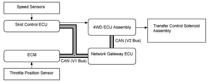
The 4WD ECU assembly controls the transfer control solenoid assembly based on the throttle position sensor and 4 speed sensors. The solenoid controls the hydraulic pressure applied to the center differential limiting clutch. Thus, acceleration control will be performed.
-
If the difference between the front wheel speed and the rear wheel speed exceeds the specified value while driving at a medium or high speed, the 4WD ECU assembly, in accordance with the throttle valve angle, increases the hydraulic pressure applied to the center differential limiting clutch to directly couple the center differential. This prevents the rear wheels from slipping and stabilizes the vehicle.
-
-
-
CONSTRUCTION
-
Transfer Assembly
-
The UF1AE transfer is compact and lightweight, with a center differential device and a center differential limiting device placed coaxially to the transmission output shaft. The basic hydraulic pressure of the transmission is shared by the center differential limiting device to effect its control.
-
The center differential uses a planetary gear system consisting of single planetary gear set with 4 pinions.
-
The center differential limiting device uses a wet type multi-disc clutch.
-
A silent chain is used to transmit the driving force to the front wheels, which prevents the side of the transfer case from bulging out.
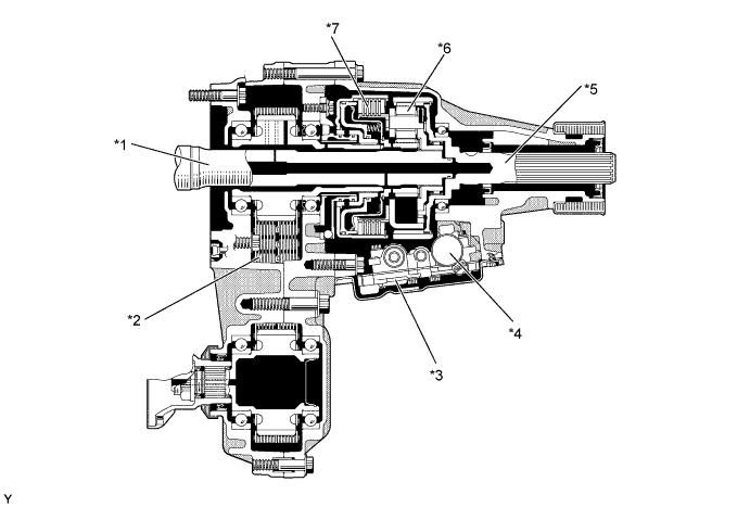
Text in Illustration *1 Transmission Output Shaft (Rear Planetary Carrier Sub-assembly) *2 Transfer Front Drive Chain *3 Transfer Control Valve Body Assembly *4 Transfer Control Solenoid Assembly *5 Transfer Rear Output Shaft Assembly *6 Center Differential *7 Transfer Direct Clutch Assembly - -
-
-
Center Differential Mechanism
-
The center differential distributes the driving force from the transmission to the front and rear wheels. In addition, the center differential absorbs the rotational difference between the front and rear drive shafts that is created during cornering.
-
A planetary gear is used for the center differential, which unevenly distributes the driving force to the front and rear wheels.
-
The center differential receives the driving force that is input by the transmission by way of the planetary carrier. The planetary carrier and the sun gear are controlled by the center differential limiting device until they are in the lock-up state.
-
A compact, lightweight and extremely silent chain is used for the front wheel drive transmission, and the driving force is transferred to the front wheel drive shaft by the sun gear of the center differential. The driving force to the rear wheel drive shaft is output coaxially with the transmission by way of the ring gear of the center differential.
-
When the center differential limiting device is not operating, drive force is unevenly distributed 30:70 (front:rear) in accordance with radius difference between the sun gear and ring gear. However, during center differential limiting device operation, drive force is variably controlled from 30:70 to 50:50. The drive force is distributed 50:50 when the center differential limiting clutch is engaged.
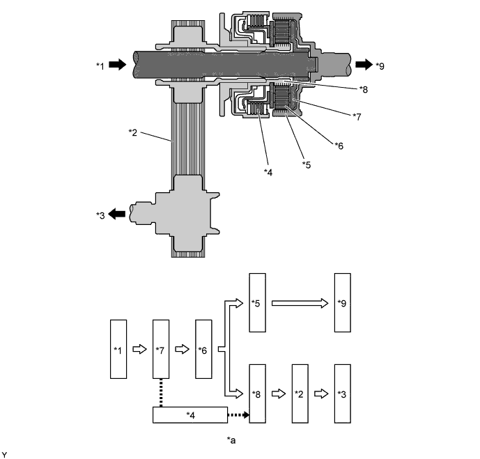
Text in Illustration *1 Transmission *2 Transfer Front Drive Chain *3 Front Propeller Shaft *4 Transfer Direct Clutch Assembly *5 Center Differential Planetary Ring Gear *6 Center Differential Planetary Pinion *7 Center Differential Planetary Carrier *8 Center Differential Planetary Sun Gear *9 Rear Propeller Shaft - - *a Power Flow - -
-
-
Center Differential Limiting Clutch
-
The center differential limiting clutch is located between the planetary gear and the front wheel drive force distribution section. The center differential limiting clutch consists of wet type clutch discs, plates, and a piston. Its basic construction is the same as the clutch of an automatic transmission.
-
This clutch utilizes the friction resistance, which is created by the speed difference that occurs between the plates and discs, to transmit and distribute torque to the center differential limiting device and the front and rear wheels.
-
Adjustment of the differential control limiting force is controlled by changing the hydraulic pressure that functions in the piston.
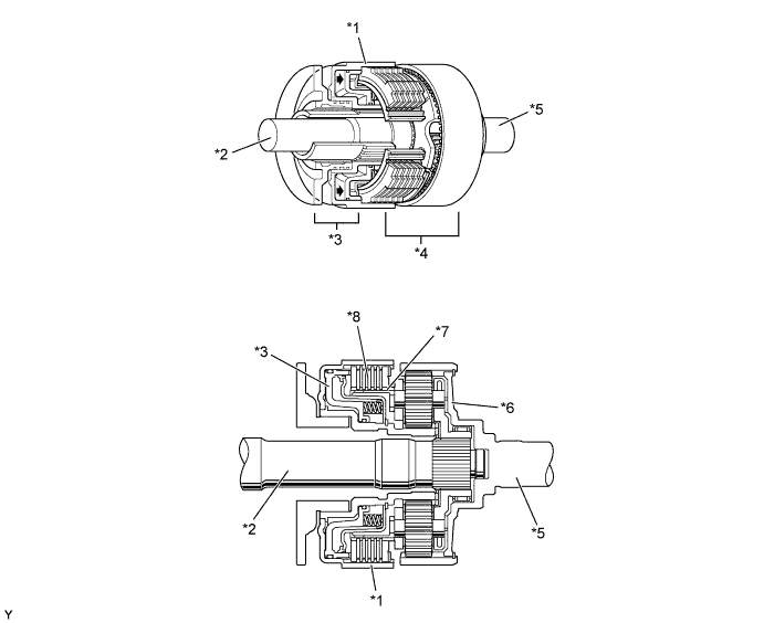
Text in Illustration *1 Transfer Direct Clutch Drum *2 Transmission Output Shaft (Rear Planetary Carrier Sub-assembly) *3 Center Differential Clutch Piston *4 Center Differential *5 Transfer Rear Output Shaft Assembly *6 Center Differential Planetary Carrier *7 Center Differential Clutch Hub *8 Transfer Direct Clutch Assembly
-
-
Hydraulic Control (Line Pressure Control)
-
Line pressure for transmission control is also used by the transfer to simplify the transfer hydraulic system.
-
Line pressure from the transmission is controlled by a modulator valve so that it does not rise above a specific level. This stabilizes hydraulic control of the transfer control solenoid assembly.
-
Hydraulic pressure controlled by the transfer control solenoid assembly operates the control valve. The pressure also controls the slip status of the center differential limiting clutch by modulating the line pressure from the transmission in the transfer control solenoid assembly.
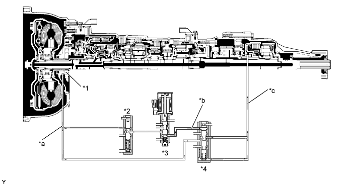
Text in Illustration *1 Oil Pump *2 Modulator Valve *3 Transfer Control Solenoid Assembly *4 Control Valve *a Line Pressure *b Control Pressure *c Clutch Engagement Pressure - -
-
-
Valve Body
-
The valve body, which is located in the bottom of the transfer case, has a 2-stage composition consisting of an upper valve body and a valve body cover. The transfer control solenoid assembly is installed in the upper valve body.
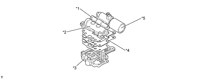
Text in Illustration *1 Modulator Valve Portion *2 Control Valve Portion *3 Valve Body Cover *4 Upper Valve Body *5 Transfer Control Solenoid Assembly - -
-
-
Transfer Control Solenoid Assembly
-
The transfer control solenoid assembly is integrated with the electromagnetic section and the pressure modulating section. The spool pushes the pressure modulating valve in accordance with the electric current value that makes the electromagnetic section function. The pressure modulating valve then generates hydraulic pressure to resist the pushing force of the spool, thus making it possible to obtain hydraulic pressure proportional to the electric current value.

Text in Illustration *1 Pressure Modulating Valve *2 Spool *3 Electromagnetic Section - -
-
-
-
FAIL-SAFE
-
The fail-safe function minimizes the loss of operability when an abnormality occurs in a sensor or a solenoid.
-
For details, refer to the Repair Manual.
-
-
DIAGNOSIS
-
When the 4WD ECU assembly detects a malfunction, it makes a diagnosis and memorizes the failed section. Furthermore, the master warning light illuminates and the multi-information display indicates to inform the driver.
-
The 4WD ECU assembly will also store the Diagnostic Trouble Codes (DTCs) of the malfunctions.
-
The DTCs can be read by connecting the SST (09843-18040) between the TC and CG terminals of DLC3 and they are shown on the multi-information display, or by connecting a Global Tech Stream (GTS) to the DLC3.
-
For details, refer to the Repair Manual.
-