AUTOMATIC TRANSMISSION SYSTEM DETAILS
-
FUNCTION OF MAIN COMPONENTS
Component Function ATF Warmer*1
-
Warms up the ATF quickly.
-
Keeps the ATF temperature higher (within limits).
Torque Converter Assembly
-
Transmits the engine power to the transmission.
-
Increases engine torque.
Oil Pump Provides oil pressure necessary for the transmission operation. No. 1 Clutch (C1) Connects the front planetary ring gear and rear sun gear. No. 2 Clutch (C2) Connects the intermediate shaft and rear planetary carrier. No. 3 Clutch (C3) Connects the front planetary ring gear and middle sun gear. No. 4 Clutch (C4) Connects the front planetary carrier and middle sun gear. No. 1 Brake (B1) Prevents the middle sun gear from turning either clockwise or counterclockwise. No. 2 Brake (B2) Prevents the rear planetary carrier from turning either clockwise or counterclockwise. No. 1 1-way Clutch (F1) Prevents the rear planetary carrier from turning counterclockwise. Planetary Gears Change the power transmission route in accordance with clutch and brake operation, and increase or decrease output shaft revolution accordingly. Shift Solenoid Valve SL1 Controls No. 1 clutch (C1) pressure. Shift Solenoid Valve SL2 Controls No. 2 clutch (C2) pressure. Shift Solenoid Valve SL3 Controls No. 3 clutch (C3) pressure. Shift Solenoid Valve SL4 Controls No. 4 clutch (C4) pressure. Shift Solenoid Valve SL5 Controls No. 1 brake (B1) pressure. Shift Solenoid Valve SLU (Lock Up Control Solenoid Assembly)
-
Controls lock-up clutch pressure.
-
Controls No. 2 brake (B2) pressure.
Shift Solenoid Valve SLT (Line Pressure Control Solenoid Assembly) Controls line pressure. Shift Solenoid Valve SL (Transmission 3-way Lock Up Solenoid Assembly)
-
Switches the lock-up relay valve.
-
Switches the reverse control valve.
Shift Solenoid Valve SR (Shift Solenoid Valve DSL)
-
Switches the clutch control valve.
-
Switches the sequence control valve.
ATF Temperature Sensor Detects the ATF temperature. Oil Pressure Switch Monitors output fluid pressure of each shift solenoid valve. Transmission Revolution Sensor (NT) Detects the input speed of the transmission. Transmission Revolution Sensor (NC3) Detects the speed of the intermediate shaft. Transmission Revolution Sensor (SP2) Detects the output speed of the transmission. Yaw Rate Sensor
-
Detects the vehicle's longitudinal and lateral acceleration.
-
Detects the vehicle's yaw rate.
Park/Neutral Position Switch Assembly Detects the shift lever position (P, R, N, D). Transmission Control Switch
-
Detects that the shift lever is in M.
-
Detects the driver's shift-up and shift-down operations when the shift lever is in M.
Shift Paddle Switch (Transmission Shift Switch Assembly) Detects the driver's shift-up and shift-down operations. Stop Light Switch Assembly Detects the brake pedal depressing signal. Kick Down Switch Assembly Detects that the accelerator pedal is almost fully depressed. Combination Switch Assembly Drive Mode Select Selects the drive mode (NORMAL, SPORT, SPORT S or SPORT S+). SNOW Switch*2 Selects the SNOW mode. Combination Meter Assembly MIL Illuminates or blinks to inform the driver when the ECM detects a malfunction. Multi-information Display
-
Displays the shift lever position.
-
Displays the shift range.
-
Displays the gear position.
-
Displays the drive mode.
-
Displays the message when the ATF is at a high temperature.
-
Displays the gear shift indicator.*3
Multi Buzzer Sounds when shift-down operation is rejected in M mode. TCM
-
Controls each shift solenoid valve in response to a signal from each sensor and switch.
-
When the TCM detects a malfunction, the TCM makes a diagnosis and memorizes the failed section.
ECM Controls engine output in response to a signal from the TCM. Skid Control ECU Sends the information about the operation conditions of the brake control system to the ECM. Driving Support ECU Assembly*4 Sends the information about the operation conditions of the dynamic radar cruise control system to the ECM.
-
*1: Except models for G.C.C. countries and models for Australia and general countries with towing package
-
*2: Except models for G.C.C. countries
-
*3: The Gear Shift Indicator system may not be provided depending on the destination.
-
*4: Models with dynamic radar cruise control system
-
-
SYSTEM CONTROL
-
The electronic control system of the AA80E automatic transmission consists of the control functions listed below:
Control Function Powertrain Cooperative Control Controls both the shift control and engine output control in an integrated way, thus achieving excellent shift characteristics and driveability. Shift Timing Control The TCM sends current to each shift solenoid valve based on signals from various sensors in order to shift the gears. Line Pressure Control Actuates the shift solenoid valve SLT (line pressure control solenoid assembly) to control the line pressure in accordance with information from the TCM and the operating conditions of the transmission. Clutch Pressure Optimal Control The shift solenoid valves SL1, SL2, SL3, SL4, SL5, SLT (line pressure control solenoid assembly) and SLU (lock up control solenoid assembly) minutely control the clutch pressure in accordance with the engine output and driving conditions of the transmission. Clutch to Clutch Pressure Control Controls the pressure that is applied directly to brake B1 and each clutch by actuating the shift solenoid valves SL1, SL2, SL3, SL4 and SL5 in accordance with the TCM signals. Multi-mode Automatic Transmission
-
The TCM appropriately controls the automatic transmission in accordance with the shift range or gear range selected using the shift lever or shift paddle switch (transmission shift switch assembly) while the shift lever is in M.
-
An improvement in manual operation response and driveability has been achieved by the gear hold control, high response upshift control and blipping downshift control.
-
When the shift lever is in D, the driver can select a desired shift range using the shift paddle switch (transmission shift switch assembly).
Linear Feel Improving Control This control reduces the frequency of downshifting by utilizing the engine torque of each gear range as much as possible. Also, by reducing the differences in drive force generated before and after downshifting, linear dynamic characteristics have been achieved. Coast Downshift Control To prevent the engine speed from decreasing and maintain the fuel cut, the TCM performs downshifts before fuel cut ends. Lock-up Timing Control The TCM sends current to the shift solenoid valve SLU (lock up control solenoid assembly) based on signals from various sensors and engages or disengages the lock-up clutch. Flex Lock-up Clutch Control Controls the shift solenoid valve SLU (lock up control solenoid assembly), provides an intermediate mode for when the lock-up clutch is between on and off, and increases the operating range of the lock-up clutch to improve fuel economy. Artificial Intelligence Shift Control (AI-shift Control) Based on the signals from various sensors, the TCM determines the road conditions and the intention of the driver. Thus, an appropriate shift pattern is automatically determined, which improves driveability. 2nd Gear Start-off and Stop Control When the engine idling speed is high while the engine is warming up and the road surface is slippery, 2nd gear start-off and stop control for low-friction roads is automatically used in order to enhance control of the driving force using the accelerator. Differential Protection Control
-
When there is a large rotation difference between the left and right wheels, shifting will be prevented to protect the differential.
-
The TCM regulates engine torque down control to protect the differential when in 1st gear.
ATF High Temperature Control When the ATF is at a high temperature, normal shifting characteristics will be changed to shifting characteristics which actively utilize the low gear range to prevent the oil temperature from rising further. -
-
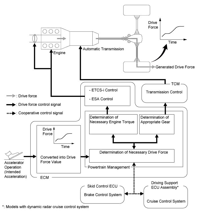
Powertrain Cooperative Control
-
The Driving Response and Acceleration Management System (DRAMS) is used for this vehicle. This system integrally controls the engine, transmission and other driving related controls. By integrally controlling the engine and automatic transmission using this system, quick response and a high quality driving feel in accordance with the driver's intentions are achieved, such as when accelerating or decelerating or during gear shifts.
-
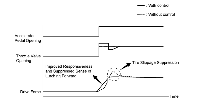
Throttle Control at Launch
-
The engine output is optimally controlled with the Electronic Throttle Control System-intelligent (ETCS-i) in real time in accordance with the transient force from the torque converter when the vehicle starts off. This achieves a "suppressed sense of lurching forward", "tire slippage suppression" and "improved responsiveness", ensuring excellent performance when starting off.
-
-
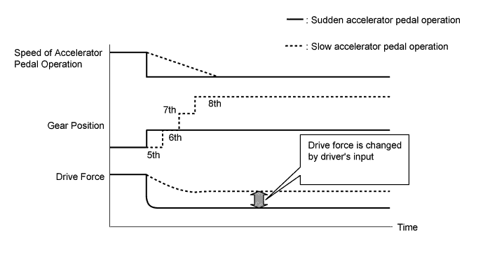
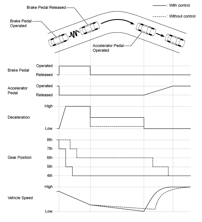
Deceleration Force Control
-
The TCM determines the gear position when the accelerator pedal is off (released completely) in accordance with the way the accelerator pedal is released (suddenly or slowly) during deceleration. In this way, unnecessary upshifts and downshifts are prevented when the accelerator pedal is off and subsequent smooth acceleration is ensured, matching the driver's intentions.
-
-
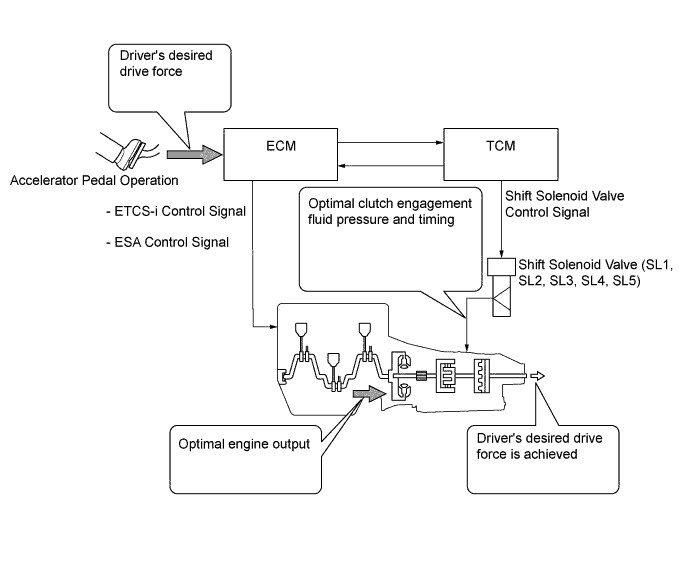
Transient Shifting Control
-
Through integrated control with the Electronic Throttle Control System-intelligent (ETCS-i), Electronic Spark Advance (ESA), and electronic control of the engagement and release speed of the clutch and brake fluid pressures, excellent response and shift shock reduction have been achieved.
-
-
-
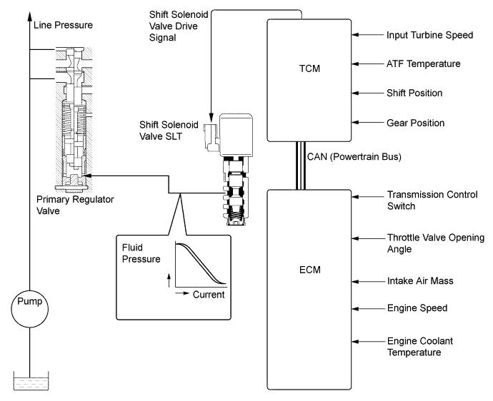
Line Pressure Control
-
The line pressure is controlled by using shift solenoid valve SLT (line pressure control solenoid assembly). Through the use of shift solenoid valve SLT (line pressure control solenoid assembly), the line pressure is optimally controlled in accordance with the engine torque information, as well as with the internal operating conditions of the torque converter and the transmission. Accordingly, the line pressure can be accurately controlled in accordance with the engine output, traveling condition and the ATF temperature, achieving smooth shift characteristics and optimizing the workload of the oil pump.
-
-
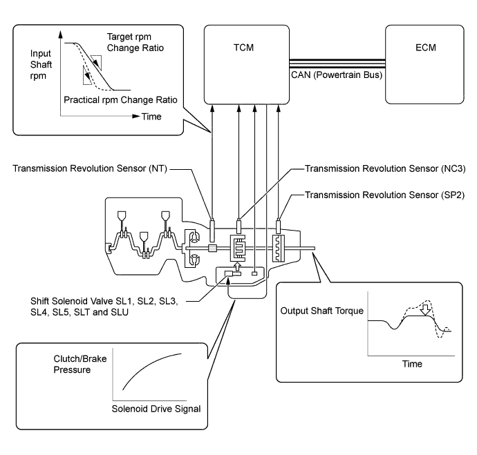
Clutch Pressure Optimal Control
-
The TCM monitors the signals from various types of sensors, such as the transmission revolution sensor (NT) and transmission revolution sensor (NC3), allowing shift solenoid valve SL1, SL2, SL3, SL4, SL5, SLT (line pressure control solenoid assembly) and shift solenoid valve SLU (lock up control solenoid assembly) to minutely control the clutch pressure in accordance with engine output and driving conditions. As a result, smooth shift characteristics are achieved.
-
-
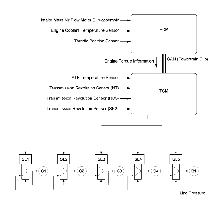
Clutch to Clutch Pressure Control
-
Clutch to clutch pressure control is used for shift control. As a result, shift control in 2nd gear or above is possible without using the 1-way clutch, and the automatic transmission has been made lightweight and compact.
-
Using the fluid pressure circuit, which enables the clutches and brakes (C1, C2, C3, C4 and B1) to be controlled independently, and the high flow SL1, SL2, SL3, SL4 and SL5 shift solenoid valves, which directly control the line pressure, the TCM controls each clutch and brake accordingly with the optimum fluid pressures and timings in accordance with the information transmitted by the sensors, and then shifts the gears. As a result, highly responsive and excellent shift characteristics have been achieved.
-
-
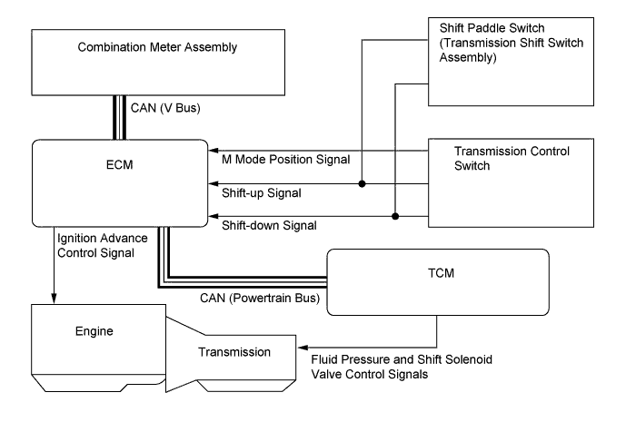
Multi-mode Automatic Transmission
-
The driver can select the desired gear range by moving the shift lever to "+" (forward) or to "- " (backward) while the shift lever is in M. Also, the shift paddle switch (transmission shift switch assembly) can be used to change the gear range while the driver is holding the steering wheel. Thus, the driver is able to shift gears with a manual-like feel.
-
When the shift lever is in D, the driver can momentarily select a desired shift range by operating the shift paddle switch (transmission shift switch assembly). Automatic shifting will be reinstated under the following conditions:
-
The vehicle has stopped.
-
The driver continues to push the shift paddle switch (transmission shift switch assembly) in the "+" direction longer than 1 second.
-
The driver depresses the accelerator pedal for more than a predetermined amount of time.
-
-
When the vehicle is being driven at a prescribed speed or higher, any attempt to shift to a lower range by operating the shift lever will not be executed, in order to protect the automatic transmission. In this case, the ECM sounds the multi buzzer in the combination meter assembly twice to alert the driver.
-
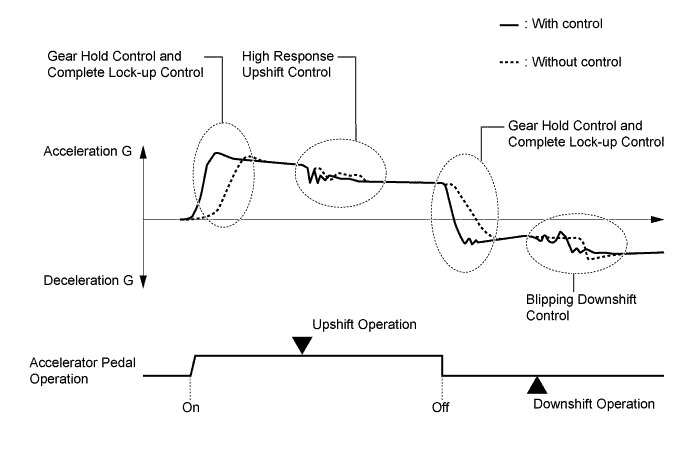
When the shift lever is in M, the gear hold control, complete lock-up control, high response upshift control and blipping downshift control are used in order to improve response in accordance with the driver's operation of the accelerator pedal, shift lever or transmission shift switch, and to improve gear shift feeling.
-
Gear Hold Control
-
Gear shifting will not be performed under gear hold control as long as the shift lever or shift paddle switch (transmission shift switch assembly) is not operated. This makes it possible to make efficient use of the highest engine speeds. However, in the following cases, operation of gear hold control is limited.
Automatic Shifting When Shift Lever is in M
-
When the ATF or engine coolant temperature is low, gear shifting will be performed automatically.
-
When the ATF temperature is high, gear shifting will be performed automatically.
-
-
-
Complete Lock-up Control
-
While the shift lever is in M, lock-up control operates from 2nd gear, transmitting the changes in engine power directly to the output shaft, the same way as with a manual transmission. As a result, direct response to the accelerator operation is achieved.
-
-
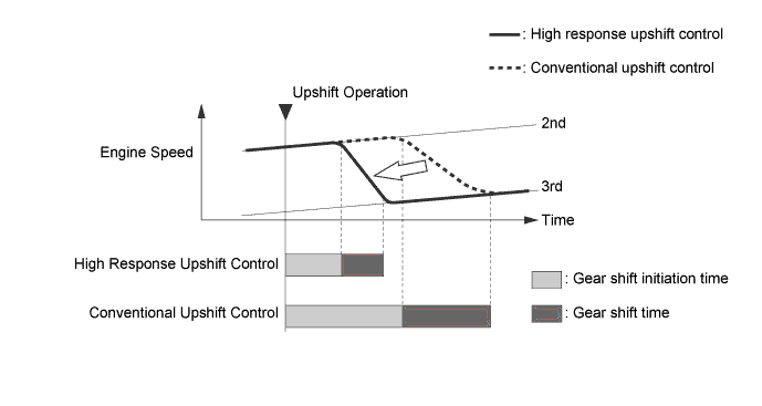
High Response Upshift Control
-
The high response upshift control achieves a highly responsive upshift operation using the clutch to clutch pressure control, which regulates each clutch and brake quickly and precisely, and using the powertrain cooperative control, which optimally regulates engine torque during shifting.
-
-
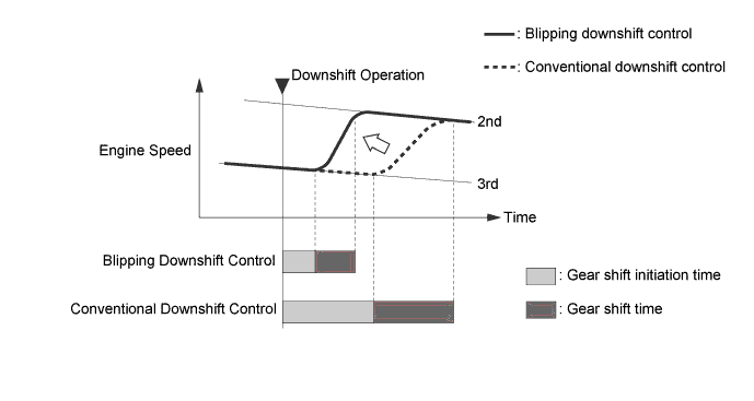
Blipping Downshift Control
-
The blipping downshift control regulates each clutch and brake using the clutch to clutch pressure control, allowing them to be engaged smoothly and disengaged quickly. In addition, fuel injection volume is increased and engine speed is boosted by the powertrain cooperative control, ensuring engine brake force. In this way, a smooth and quick downshift is achieved.
-
-
-
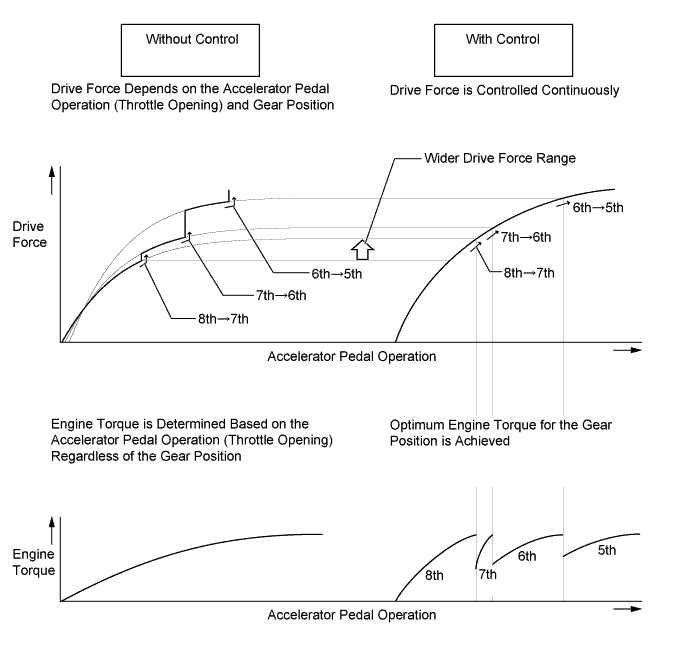
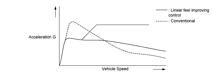
Linear Feel Improving Control
-
Conventionally, drive force was dependent on the accelerator pedal operation (throttle opening) and the gear position.
-
With the linear feel improving control, optimum engine torque (throttle opening) for the gear position is achieved, reducing the frequency of downshifting.
-
Continuous drive force has been achieved by reducing the variations in drive force when downshifting, improving controllability of the vehicle during accelerator pedal operation.
-
By reducing changes in the acceleration rate while the vehicle speed increases, a steady linear increase in vehicle speed that does not depend on the shift range has been achieved.
-
-
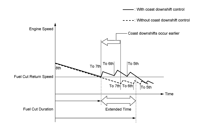
Coast Downshift Control
-
The TCM performs downshift control to prevent the engine speed from decreasing, thus keeping fuel cut control operating for as long as possible. In this way, the fuel economy is improved.
-
In this control, the transmission downshifts from 8th to 7th, 7th to 6th and then 6th to 5th before fuel cut control ends when the vehicle is decelerated in the 8th gear, so that fuel cut control continues operating. In addition, the TCM performs downshifting when the vehicle is decelerated both in the 6th and 7th gears.
-
-
Lock-up Timing Control
-
The TCM operates the lock-up timing control in order to improve the fuel consumption performance.
Lock-up Timing Control Operation Gear Shift Lever Position Shift Range Position M D D8 D7 D6 1st X X X X X 2nd ○ X X X X 3rd ○ X X X X 4th ○ X X X X 5th ○ X X X X 6th ○ ○ ○ ○ ○ 7th ○ ○ ○ ○ - 8th ○ ○ ○ - - Tech Tips
○: Operates
X: Does not operate
-: Not applicable
-
-
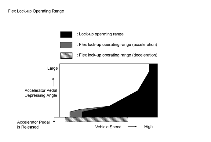
Flex Lock-up Clutch Control
-
In the low-to-mid-speed range, this flex lock-up clutch control regulates the shift solenoid valve SLU (lock up control solenoid assembly) to provide an intermediate mode between the on and off operations of the lock-up clutch in order to improve the energy transmitting efficiency. As a result, the operating range of the lock-up clutch has been increased and fuel economy has been improved.
Flex Lock-up Clutch Control Operation Gear Shift Lever Position Shift Range Position D D8 D7 D6 D5 1st X X X X X 2nd X X X X X 3rd X X X X X 4th ○ ○ ○ ○ ○ 5th [○] [○] [○] [○] [○] 6th [○] [○] [○] [○] - 7th [○] [○] [○] - - 8th [○] [○] - - - Tech Tips
[○]: Flex lock-up clutch control operates during deceleration.
○: Operates
X: Does not operate
-: Not applicable
-
-
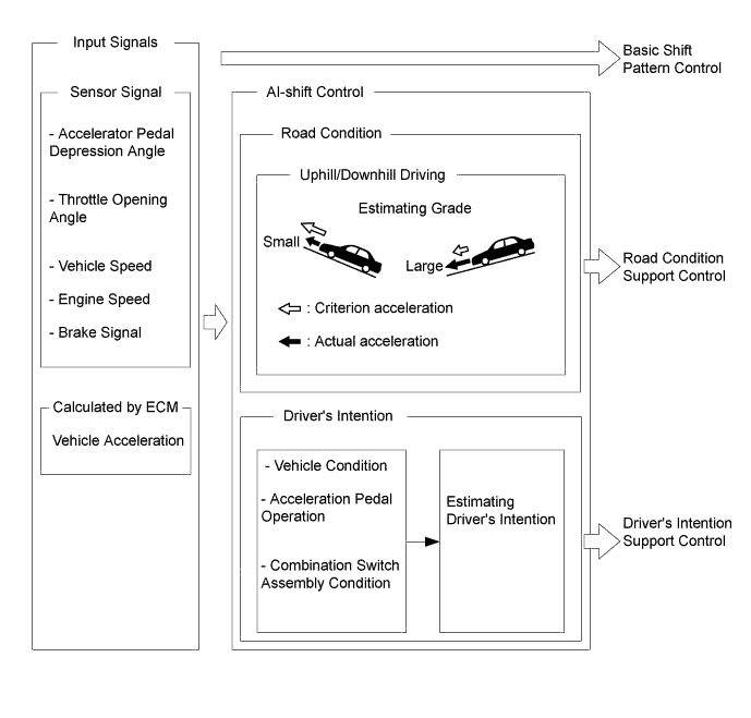
Artificial Intelligence Shift Control (AI-shift Control)
-
The AI-shift control determines optimal transmission control based on input signals and automatically changes the shift pattern. As a result, excellent transmission operation is achieved.
-
The AI-shift control includes a road condition support control and a driver's intention support.
-
The AI-shift control is performed only with the shift lever in D, based on the accelerator pedal and brake operation data. The AI-shift control will be canceled when the shift lever is moved to any position other than D.
-
Road Condition Support Control
-
The TCM identifies the throttle valve opening angle, accelerator pedal opening angle and vehicle speed to determine whether the vehicle is being driven uphill or downhill. Unnecessary upshift is restrained to automatically achieve optimal drive force at all times while driving uphill. Downshift is automatically conducted to achieve optimal engine brake force, while driving downhill.
-
-
Driver's Intention Support Control
-
The driver's intention is estimated based on the accelerator pedal operation and vehicle condition, and a shift pattern that is well-suited to the driver's intention is selected without operating the combination switch assembly.
-
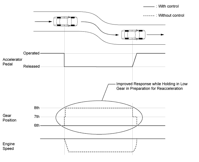
Sudden Accelerator Pedal Release Control
-
When the accelerator pedal is released suddenly, the transmission is kept in gear as long as possible, which improves engine braking force.
-
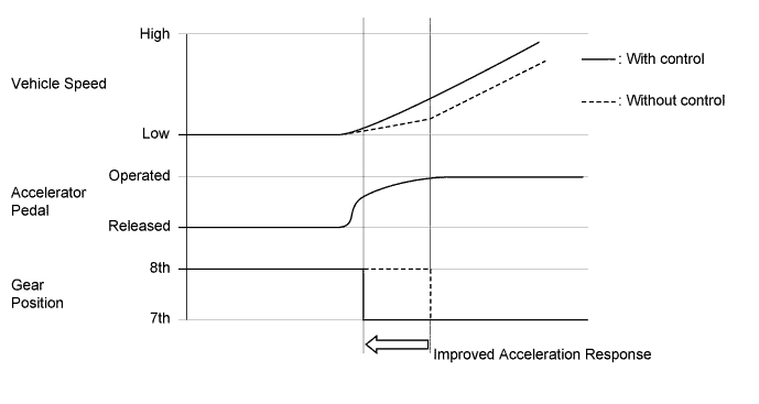
Sudden Accelerator Pedal Depress Control
-
When the accelerator pedal is depressed suddenly, downshifting occurs earlier, providing improved acceleration response.
-
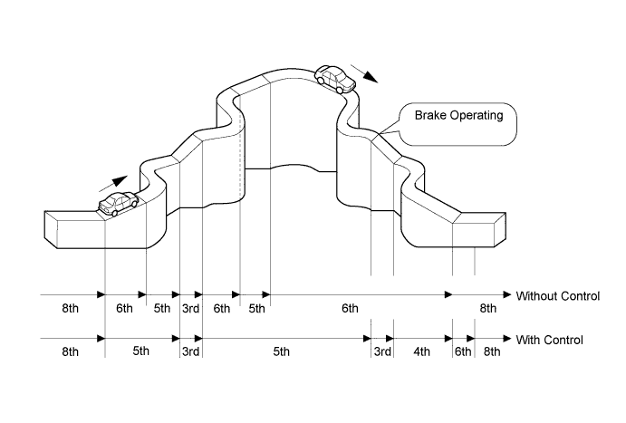
Downshift Control during Hard Braking
-
High engine braking power and good reacceleration response have been achieved by actively downshifting during deceleration when hard braking is performed.
-
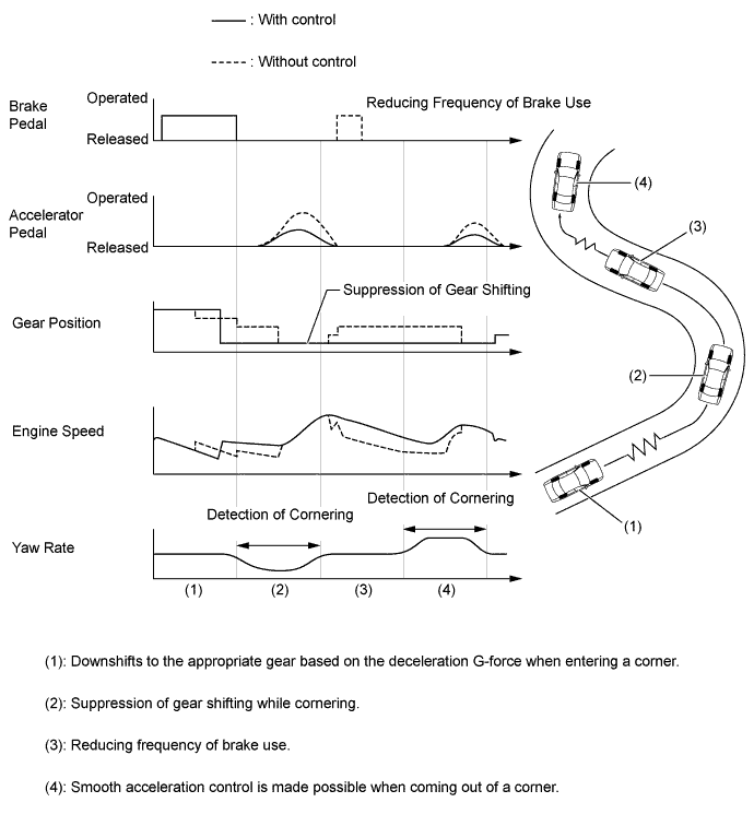
G AI-shift Control
-
When the vehicle enters a corner, this system assesses the overall vehicle condition based on signals from the G-sensor and the driver's intention, and downshifts to the appropriate gear to obtain the necessary driving force for coming out of a corner.
-
Controllability during cornering is ensured by suppressing gear shifting.
-
-
-
-
FUNCTION
-
Drive Mode Select Function
-
The drive mode can be selected by operating the drive mode select or SNOW switch.
-
The selected drive mode will be shown on the multi-information display in the combination meter assembly.
-
The drive characteristics of each drive mode are as follows:
Drive Mode Outline ECO Mode Transmission characteristics which prioritize fuel-efficient driving are used to ensure low fuel consumption compared with that of NORMAL mode. NORMAL Mode This drive mode provides optimum driveability. SPORT Mode*1
SPORT S Mode*2
The ECM improves acceleration performance and responsiveness by controlling the opening of the throttle and by changing the shift point of the transmission, achieving a sporty drive. SPORT S+ Mode*2 In addition to the control when in SPORT S mode, the suspension control system, brake control system and steering control system have been integrated to shift to SPORT mode, improved operability and stability without losing comfort have been aimed for and control is performed to enable operation appropriate to the driver's intention. SNOW Mode The TCM improves starting-off performance and acceleration performance on slippery road surfaces such as when the wheels spin while driving on a snowy road by controlling to restrain drive force more than when in NORMAL mode.
-
*1: Models without Adaptive Variable Suspension system (AVS)
-
*2: Models with Adaptive Variable Suspension system (AVS)
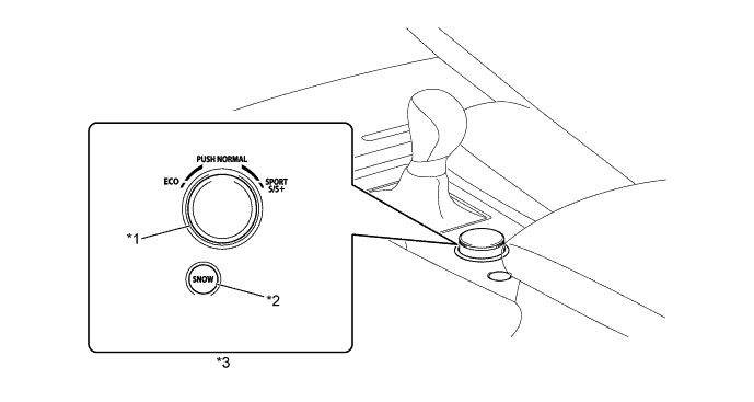
Text in Illustration *1 Drive Mode Select *2 SNOW Switch *3 Combination Switch Assembly - - -
-
-
Gear Shift Indicator System
-
The Gear Shift Indicator system is a system to promote upshifting to the fuel-efficient and optimal gear ranges in accordance with the driving conditions such as the accelerator pedal opening and the vehicle speed, etc. when the vehicle is running while the shift lever is in M.
-
By driving in accordance with the upshifting recommendations indicated by the multi-information display in the combination meter assembly and headup display, the driver can enhance environmental performance, improve fuel economy and reduce exhaust gas emissions within the limits of engine performance.
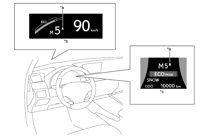
Text in Illustration *a Gear Shift Indicator *b Headup Display *c Multi-information Display - -
-
-
Shift Lock System
-
The shift lock system prevents the shift lever from being moved to any position other than P, unless the engine switch is turned on (IG) and the brake pedal is depressed. This prevents the vehicle from starting off suddenly.
-
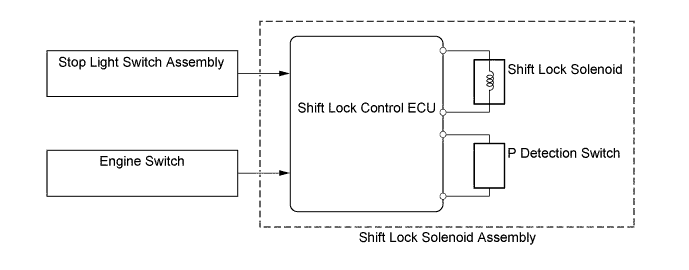
The shift lock system is controlled by the shift lock control ECU sub-assembly, and the system has a shift lock function.
-
The shift lock control ECU sub-assembly has a built-in P detection switch to detect the shift lever position, and receives input signals from the stop light switch assembly and engine switch. Upon receiving these signals, the shift lock control ECU sub-assembly turns on the shift lock solenoid in order to release the shift lock.
-
A shift lock release button, which manually overrides the shift lock mechanism, is used.
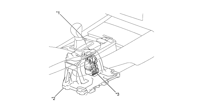
Text in Illustration *1 Shift Lock Release Button *2 Transmission Floor Shift Assembly *3 Shift Lock Solenoid Assembly
-
Shift Lock Control ECU
-
P Detection Switch
- - 
-
-
-
-
CONSTRUCTION
-
ATF Warmer
-
The ATF warmer uses engine coolant that has been warmed by the engine to warm up the ATF quickly and to keep the ATF temperature at a high level (within limits). Consequently, the friction losses of the automatic transmission are quickly reduced, improving fuel economy.
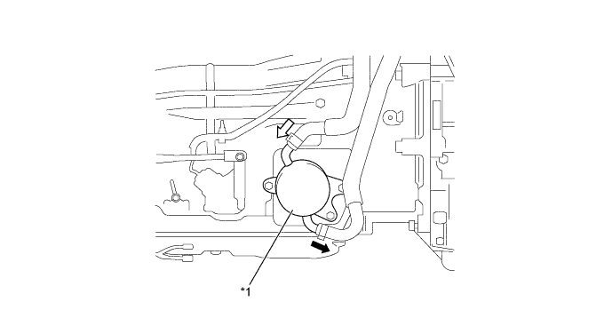
Text in Illustration *1 ATF Warmer - - 
Engine Coolant Flow (to Engine) 
Engine Coolant Flow (from Engine)
-
-
Torque Converter
-
A compact, lightweight and high-capacity torque converter assembly is used. The torque converter supports lock-up clutch control, improving fuel economy.
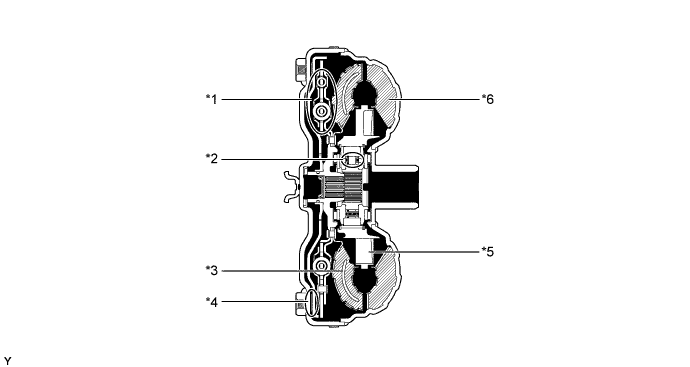
Text in Illustration *1 Lock-up Damper *2 1-way Clutch *3 Turbine Runner *4 Lock-up Clutch *5 Stator *6 Pump Impeller
-
-
Oil Pump
-
The oil pump is operated by the torque converter. The oil pump lubricates the planetary gear units and supplies operating fluid pressure for hydraulic control. The front oil pump drive gear is continually driven by the engine via the pump impeller. The pump has sufficient capacity to supply the necessary fluid pressure throughout all speed ranges, as well as in reverse.
-
The pump cover is made of aluminum to reduce weight.
-
A pump cover with an integrated piston cylinder for the No. 1 brake (B1) is used.
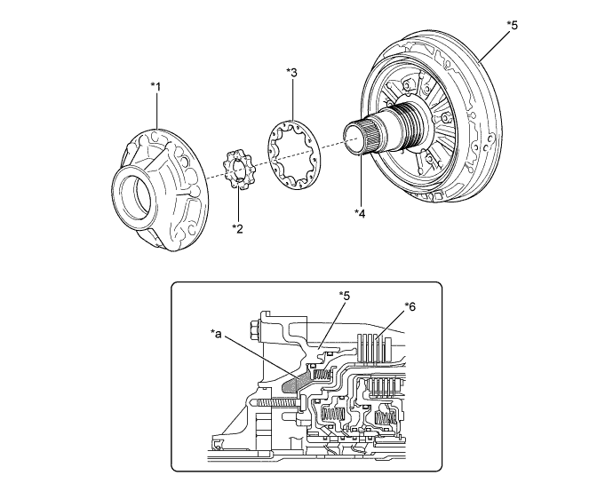
Text in Illustration *1 Pump Body *2 Drive Gear *3 Driven Gear *4 Stator Shaft *5 Pump Cover *6 No.1 Brake (B1) *a No.1 Brake (B1) Piston Cylinder - -
-
-
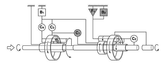
Planetary Gear Unit
-
An 8-speed configuration has been achieved by using 2 planetary gear units, creating an 8- speed automatic transmission.
-
A Ravigneaux type gear unit is used as the rear planetary gear unit. The gear unit consists of pairs of sun gears (middle and rear) and planetary pinion gears (long and short) with different diameters within a single planetary gear.
-
The centrifugal fluid pressure canceling mechanism is used in the C1, C2, C3 and C4 clutches that are applied when shifting from 2nd to 3rd, from 3rd to 4th, from 4th to 5th, from 5th to 6th, from 6th to 7th and from 7th to 8th.
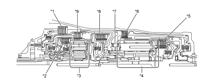
Text in Illustration *1 No. 1 Brake (B1) *2 No. 4 Clutch (C4) *3 Front Planetary Ring Gear *4 Rear Planetary Gear Unit *5 No. 2 Clutch (C2) *6 No. 2 Brake (B2) *7 No. 1 1-way Clutch *8 No. 1 Clutch (C1) *9 No. 3 Clutch (C3) - - 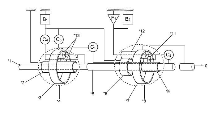
Text in Illustration *1 Input Shaft *2 Front Planetary Sun Gear *3 Front Planetary Ring Gear *4 Front Planetary Gear Unit *5 Intermediate Shaft *6 Rear Planetary Middle Sun Gear *7 Rear Planetary Ring Gear *8 Rear Planetary Gear Unit *9 Rear Planetary Rear Sun Gear *10 Output Shaft *11 Rear Planetary Short Pinion Gear *12 Rear Planetary Long Pinion Gear *13 Front Planetary Pinion Gear - - C1 No. 1 Clutch C2 No. 2 Clutch C3 No. 3 Clutch C4 No. 4 Clutch B1 No. 1 Brake B2 No. 2 Brake F1 No. 1 1-way Clutch - -
-
-
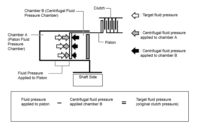
Centrifugal Fluid Pressure Canceling Mechanism
-
The clutch engagement force during shift transmission is affected by the centrifugal fluid pressure that acts on the fluid inside the piston fluid pressure chamber (referred to as "chamber A"), in addition to the original clutch pressure regulated by the valve body. In order to eliminate the influence caused by the centrifugal fluid pressure, the canceling fluid pressure chamber (referred to as "chamber B") is provided on the opposite side of chamber A to cancel out the centrifugal fluid pressure. As a result, the centrifugal fluid pressure canceling mechanism provides responsive and smooth shift transmission.
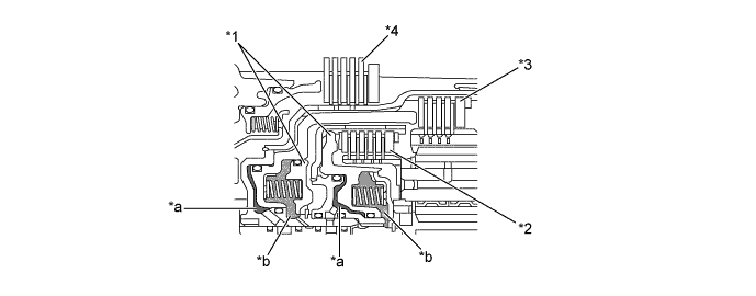
Text in Illustration *1 Piston *2 No. 4 Clutch (C4) *3 No. 3 Clutch (C3) *4 No. 1 Brake *a Chamber A *b Chamber B -
Chamber B is filled by fluid supplied to the shaft for lubrication. As a result of filling chamber B, the same amount of fluid pressure is present on both sides of the piston due to centrifugal force. This cancels the effects of fluid pressure on the piston caused by centrifugal force. Accordingly, it is not necessary to discharge the fluid through the use of a check ball, and highly responsive and smooth shifting characteristics are achieved.
-
-
Transmission Valve Body Assembly
-
The transmission valve body assembly consists of upper and lower valve bodies and 9 shift solenoid valves.
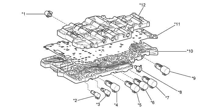
Text in Illustration *1 Shift Solenoid Valve SR (Shift Solenoid Valve DSL) *2 Shift Solenoid Valve SLT (Line Pressure Control Solenoid Assembly) *3 Shift Solenoid Valve SLU (Lock Up Control Solenoid Assembly) *4 Shift Solenoid Valve SL1 *5 Shift Solenoid Valve SL5 *6 Shift Solenoid Valve SL4 *7 Shift Solenoid Valve SL3 *8 Shift Solenoid Valve SL (Transmission 3-way Lock Up Solenoid Assembly) *9 Shift Solenoid Valve SL2 *10 Lower Valve Body *11 Plate *12 Upper Valve Body 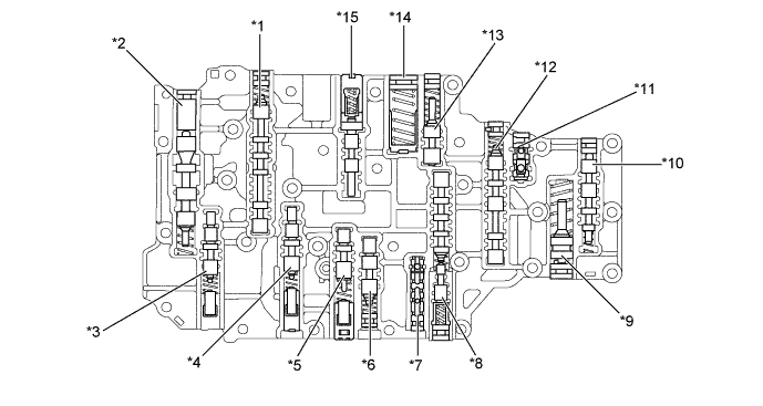
Text in Illustration (Upper Valve Body) *1 Lock-up Relay Valve *2 Solenoid Regulator Valve *3 No. 1 Clutch Apply Control Valve *4 No. 1 B1 Apply Control Valve *5 No. 2 Clutch Apply Control Valve *6 C4 Relay Valve *7 Signal Check Valve *8 No. 2 Clutch Apply Relay Valve *9 C2 Damper *10 B2 Control Valve *11 B2 Check Valve *12 No. 1 Clutch Apply Relay Valve *13 Solenoid Modulator Valve *14 C1 Accumulator Valve *15 Lock-up Control Valve - - 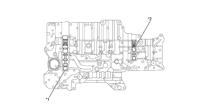
Text in Illustration (Lower Valve Body) *1 Primary Regulator Valve *2 B2 Apply Control Valve
-
-
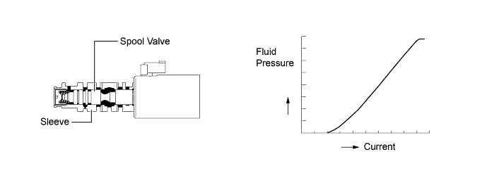
Shift Solenoid Valve SL1, SL2, SL3, SL4, SL5, SLU and SLT
-
In order to provide a fluid pressure that is proportional to the current that flows to the solenoid coil, shift solenoid valve SL1, SL2, SL3, SL4, SL5, SLU and SLT linearly control the line pressure and clutch and brake engagement pressure based on the signals from the TCM.
-
Shift solenoid valve SL1, SL2, SL3, SL4 and SL5 are large flow linear solenoid valves that can supply more pressure than conventional ones. These shift solenoid valves control engagement elements by directly regulating the line pressure without using the pressure regulation valve or the pressure reduction valve. Thus, the number of valves and the length of the valve body fluid passage have been reduced, the shifting response has been improved and the shift shock has been minimized.
-
Shift Solenoid Valve SL1, SL3, SL4 and SL5
-
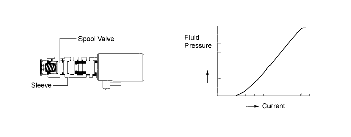
Shift Solenoid Valve SL2
-
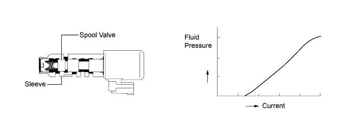
Shift Solenoid Valve SLU (Lock Up Control Solenoid Assembly)
-
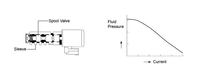
Shift Solenoid Valve SLT (Line Pressure Control Solenoid Assembly)
-
-
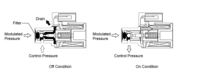
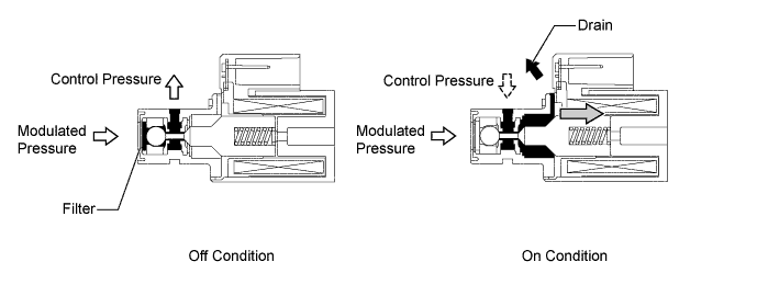
Shift Solenoid Valve SL and SR
-
A 3-way solenoid valve is used for shift solenoid valve SL and SR.
-
A filter is provided at the tip of the shift solenoid valves to further improve operational reliability.
-
Shift Solenoid Valve SL (Transmission 3-way Lock Up Solenoid Assembly)
-
Shift Solenoid Valve SR (Shift Solenoid Valve DSL)
-
-
Transmission Revolution Sensor
-
This automatic transmission uses the transmission revolution sensor (NT), transmission revolution sensor (NC3) and transmission revolution sensor (SP2). Thus, the TCM can detect the timing of the shifting of the gears and appropriately control the engine torque and fluid pressure in response to various conditions. These transmission revolution sensors are the Hall type.
-
The transmission revolution sensor (NT) detects the input speed of the transmission. The input shaft is used as the timing rotor for this sensor.
-
The transmission revolution sensor (NC3) detects the speed of the intermediate shaft. The No. 3 clutch (C3) drum is used as the timing rotor for this sensor.
-
The transmission revolution sensor (SP2) detects the speed of the output shaft. The rear planetary ring gear is used as the timing rotor for this sensor.
-
The Hall type transmission revolution sensor consists of a magnet and Hall IC. The Hall IC converts the changes in the magnetic flux density that occur through the rotation of the timing rotor into an electric signal, and outputs the signal to the TCM.
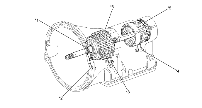
Text in Illustration *1 Input Shaft *2 Transmission Revolution Sensor (NT) *3 Transmission Revolution Sensor (NC3) *4 Transmission Revolution Sensor (SP2) *5 Rear Planetary Ring Gear *6 No. 3 Clutch Drum
-
-
ATF Temperature Sensor
-
The ATF temperature sensor is installed in the lower valve body for direct detection of the fluid temperature.
-
The ATF temperature sensor is used for the correction of the clutch and brake pressures to maintain a smooth shift quality every time.
Text in Illustration *1 Lower Valve Body *2 ATF Temperature Sensor
-
-
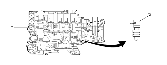
Oil Pressure Switch
-
The oil pressure switch is located in the output fluid passage of the shift solenoid valve SL1, and the switch is turned on/off in accordance with the shift solenoid valve output fluid pressure.
-
When shift solenoid valve SL1 malfunctions, the TCM determines the appropriate fail-safe operation to be actuated in accordance with the on/off signals from the oil pressure switch.
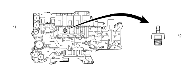
Text in Illustration *1 Lower Valve Body *2 Oil Pressure Switch
-
-
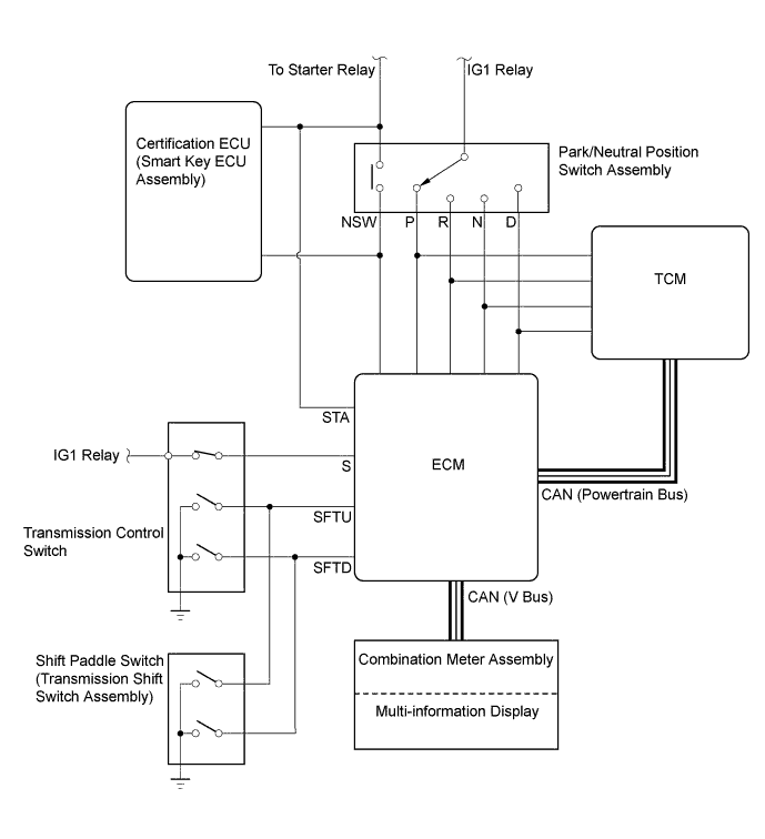
Park/Neutral Position Switch Assembly, Transmission Control Switch and Shift Paddle Switch
-
The park/neutral position switch assembly sends the P, R, N and D signals to the ECM and TCM.
-
The transmission control switch is installed inside the transmission floor shift assembly to detect the M mode position and inform the ECM.
-
The transmission control switch detects whether the shift lever is in D or M, and detects the operating conditions of the shift lever "+" (forward) or "-" (backward) when M mode is selected, and sends signals to the ECM.
-
The shift paddle switch (transmission shift switch assembly) is installed in the steering wheel. The ECM detects the operation of the shift paddle switch (transmission shift switch assembly) "+" (upshift) or "-" (downshift) when the shift lever is in D or M.
-
-
Shift Control Mechanism
-
A gate type shift lever that uses a transmission control rod is used.
-
The shift control mechanism consists of a transmission floor shift assembly and a floor shift gear shifting rod sub-assembly.
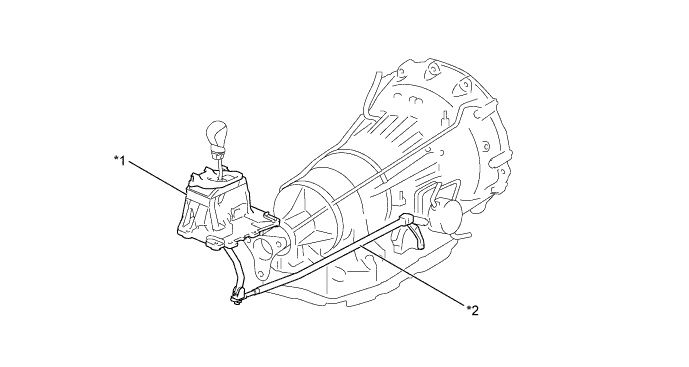
Text in Illustration *1 Transmission Floor Shift Assembly *2 Floor Shift Gear Shifting Rod Sub-assembly
-
-
-
OPERATION
-
Transmission Power Flow
Operating Condition of Shift Solenoid Valves Shift Position, Shift Range and Gear Position Shift Solenoid Valve SL1 SL2 SL3 SL4 SL5 SR SL SLU P ○ X X X X ○ X X R X X ○ X X ○ ○ X N ○ X X X X ○ X X D
D8
1st ○ X X X X ○ X X 2nd ○ X X X ○ ○ X X 3rd ○ X ○ X X ○ X X 4th ○ X X ○ X ○ ○ ▲ 5th ○ ○ X X X ○ ○ ▲ 6th X ○ X ○ X ○ ○ ▲ 7th X ○ ○ X X ○ ○ ▲ 8th X ○ X X ○ ○ ○ ▲ D7 1st ○ X X X X ○ X X 2nd ○ X X X ○ ○ X X 3rd ○ X ○ X X ○ X X 4th ○ X X ○ X ○ ○ ▲ 5th ○ ○ X X X ○ ○ ▲ 6th X ○ X ○ X ○ ○ ▲ 7th X ○ ○ X X ○ ○ ▲ D6 1st ○ X X X X ○ X X 2nd ○ X X X ○ ○ X X 3rd ○ X ○ X X ○ X X 4th ○ X X ○ X ○ ○ ▲ 5th ○ ○ X X X ○ ○ ▲ 6th X ○ X ○ X ○ ○ ▲ D5 1st ○ X X X X ○ X X 2nd ○ X X X ○ ○ X X 3rd ○ X ○ X X ○ X X 4th ○ X X ○ X ○ ○ ▲ 5th ○ ○ X X X ○ ○ ▲ D4 1st ○ X X X X ○ X X 2nd ○ X X X ○ ○ X X 3rd ○ X ○ X X ○ X X 4th ○ X X ○ X ○ ○ ▲ D3 1st ○ X X X X ○ X X 2nd ○ X X X ○ ○ X X 3rd ○ X ○ X X ○ X X D2 1st ○ X X X X ○ X X 2nd ○ X X X ○ ○ X X D1 1st ○ X X X X ○ X X M8 8th X ○ X X ○ ○ ○ ▲ M7 7th X ○ ○ X X ○ ○ ▲ M6 6th X ○ X ○ X ○ ○ ▲ M5 5th ○ ○ X X X ○ ○ ▲ M4 4th ○ X X ○ X ○ ○ ▲ M3 3rd ○ X ○ X X ○ X X M2 2nd ○ X X X ○ ○ X X M1 1st ○ X X X X ○ X X Tech Tips
○: On
X: Off
▲: In accordance with flex lock-up
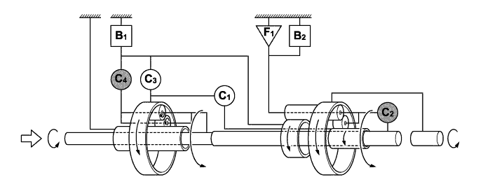
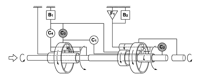
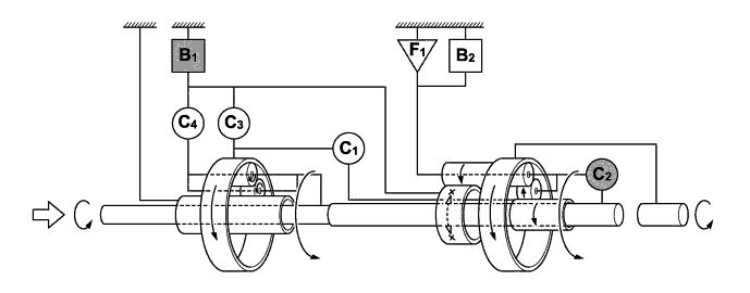
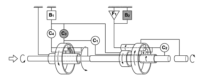
Operating Condition of Friction Engagement Components and 1-way Clutch Shift Position, Shift Range and Gear Position Clutch Brake 1-way Clutch C1 C2 C3 C4 B1 B2 F1 P - - - - - - - R - - ○ - - ○ - N - - - - - - - D
D8
1st ○ - - - - - ○ 2nd ○ - - - ○ - - 3rd ○ - ○ - - - - 4th ○ - - ○ - - - 5th ○ ○ - - - - - 6th - ○ - ○ - - - 7th - ○ ○ - - - - 8th - ○ - - ○ - - D7 1st ○ - - - - - ○ 2nd ○ - - - ○ - - 3rd ○ - ○ - - - - 4th ○ - - ○ - - - 5th ○ ○ - - - - - 6th - ○ - ○ - - - 7th - ○ ○ - - - - D6 1st ○ - - - - - ○ 2nd ○ - - - ○ - - 3rd ○ - ○ - - - - 4th ○ - - ○ - - - 5th ○ ○ - - - - - 6th - ○ - ○ - - - D5 1st ○ - - - - - ○ 2nd ○ - - - ○ - - 3rd ○ - ○ - - - - 4th ○ - - ○ - - - 5th ○ ○ - - - - - D4 1st ○ - - - - - ○ 2nd ○ - - - ○ - - 3rd ○ - ○ - - - - 4th ○ - - ○ - - - D3 1st ○ - - - - - ○ 2nd ○ - - - ○ - - 3rd ○ - ○ - - - - D2 1st ○ - - - - - ○ 2nd ○ - - - ○ - - D1 1st ○ - - - - - ○ M8 8th - ○ - - ○ - - M7 7th - ○ ○ - - - - M6 6th - ○ - ○ - - - M5 5th ○ ○ - - - - - M4 4th ○ - - ○ - - - M3 3rd ○ - ○ - - - - M2 2nd ○ - - - ○ - - M1 1st ○ - - - - - ○ Tech Tips
○: Operates
-: Does not operate
-
1st Gear (D1, M1)
Text in Illustration Input 
Operates
(B2 Operates during Engien Brake )
-
1st Gear (D, D2 to D8)
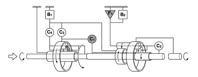
Text in Illustration Input Operates -
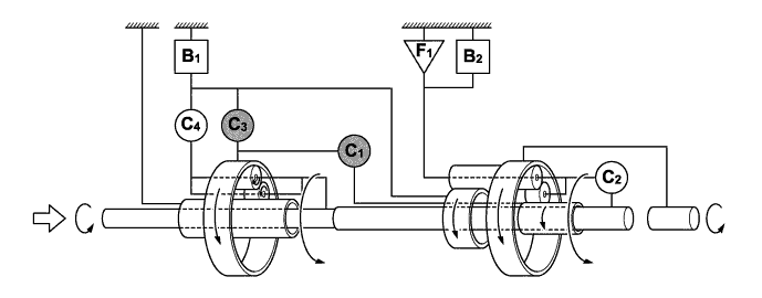
2nd Gear

Text in Illustration Input Operates -
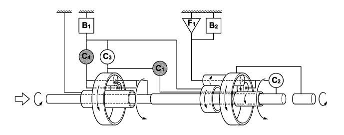
3rd Gear
Text in Illustration Input Operates -
4th Gear
Text in Illustration Input Operates -
5th Gear
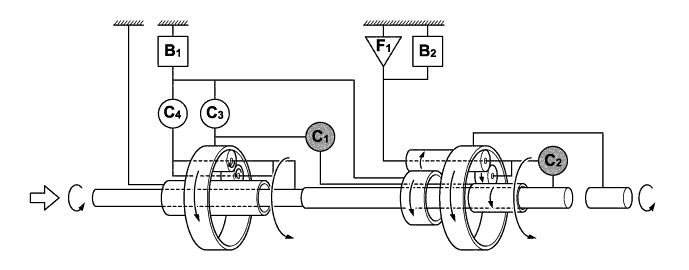
Text in Illustration Input Operates -
6th Gear
Text in Illustration Input Operates -
7th Gear
Text in Illustration Input Operates -
8th Gear
Text in Illustration Input Operates -
Reverse Gear
Text in Illustration Input Operates
-
-
-
FAIL-SAFE
-
This function minimizes the loss of operability when an abnormality occurs in a sensor or solenoid. For details, refer to the Repair Manual.
-
-
DIAGNOSIS
-
When the TCM detects a malfunction, it makes a diagnosis and memorizes the failed section. Furthermore, the TCM illuminates or blinks the MIL in the combination meter assembly to inform the driver.
-
The TCM will also store the Diagnostic Trouble Codes (DTCs) of the malfunctions.
-
The DTCs can be read by connecting a Global TechStream (GTS) to the DLC3.
-
For details, refer to the Repair Manual.
-