FRONT BODY PILLAR CUT AND JOIN REPLACEMENT SECTIONS
-
With the cowl top side upper panel and front body pillar lower gusset removed.
-
REMOVAL
Symbol Meaning 
Remove Weld Points 
Remove Weld Points 
Cut with Disc Sander etc. 
Cut and Join Location 
Cut Location for Supply Parts
-
*a in the illustration indicates the laser screw welding location.
-
Reuse A, as the area of the outer panel that is cut and joined is to the rear of the supplied part cutposition.
-
*b in illustration indicates where the adhesive is located.
-
Roughly cut open the panel so that the adhesive can be reached. Cut through the adhesive with a cut chisel to remove the panel.
Tech Tips
In cases where the adhesive cannot be removed with a cut chisel, heat the adhesive with an industrial heater gun or gas burner taking care not to cause panel deformation by overheating.
-
Carefully cut the rocker panel sub-assembly outer so not to damage B.
-
C indicates the location of the foamed sealing material. Be careful when cutting as the foamed sealingmaterial is located near the cutting position.
REMOVAL POINT
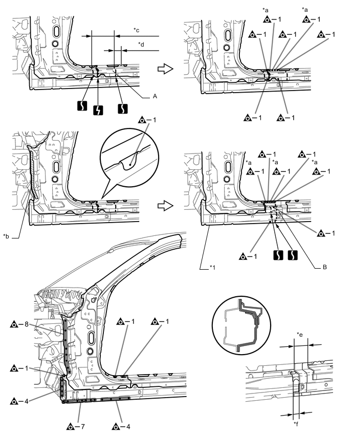
*1 ROCKER PANEL SUB-ASSEMBLY OUTER - - *c 170 mm (6.69 in.) *d 55 mm (2.17 in.) *e 80 mm (3.15 in.) *f 40 mm (1.57 in.) 
Laser Screw Welding - - 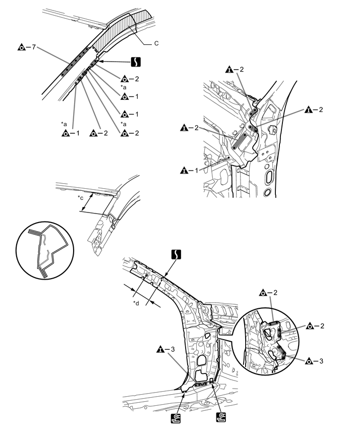
*c 140 mm (5.51 in.) *d 120 mm (4.72 in.) Laser Screw Welding - - -
-
INSTALLATION
Symbol Meaning Remove Weld Points 
Spot Weld 
Plug Weld 
Plug Weld Cut and Join Location 
Fillet Weld 
Butt Weld 
Body Sealer
-
Inspect the fitting of the related parts around the new parts before welding. This affects the appearance of the finish.
-
Temporarily install the new parts and measure each part of the new parts in accordance with the body dimension diagram. (See the body dimensions)
-
*a in the illustration indicates the laser screw welding location.
-
If the entire supply part is not needed, remove the part of the supply part that is needed.
-
A is reused.
-
Carefully cut the rocker panel sub-assembly outer so not to damage B.
-
Before temporarily installing the new parts, weld the rocker panel sub-assembly outer, front body pillar sub-assembly inner and front body pillar reinforce sub-assembly upper with the standard number of welding points.
-
Apply adhesive (3MTMAutomixTMPanel Bonding Adhesive #8115) to the area indicated by *c in the illustration.
Tech Tips
-
Apply a light coat of adhesive around the plug welding points.
-
Apply enough adhesive to the panels.
-
-
Before installing a new part, apply body sealer.
Tech Tips
Apply body sealer in an even, continuous bead.
-
C indicates the location of the foamed sealing material. Be careful when welding as the foamed sealing material is located near the area that is cut and joined together.
-
After welding the rocker panel sub-assembly outer, front body pillar sub-assembly inner and front body pillar reinforce sub-assembly upper to the vehicle side, install the D.
-
After welding the rocker panel sub-assembly outer, front body pillar sub-assembly inner, front body pillar reinforce sub-assembly upper and D to the vehicle side, install the front body pillar outer and E.
-
After welding, apply the foamed sealing material to the corresponding parts. (See the painting /coating)
-
After welding, apply body sealer to the corresponding parts. (See the painting /coating)
-
After applying the top coat, apply anti-rust agent to the internal panel portion of the closed section structural weld points.
INSTALLATION POINT
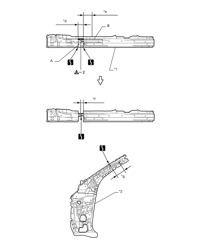
*1 ROCKER PANEL SUB-ASSEMBLY OUTER *2 FRONT BODY PILLAR SUB-ASSEMBLY INNER *d 80 mm (3.15 in.) *e 135 mm (5.31 in.) *f 40 mm (1.57 in.) *g 120 mm (4.72 in.) 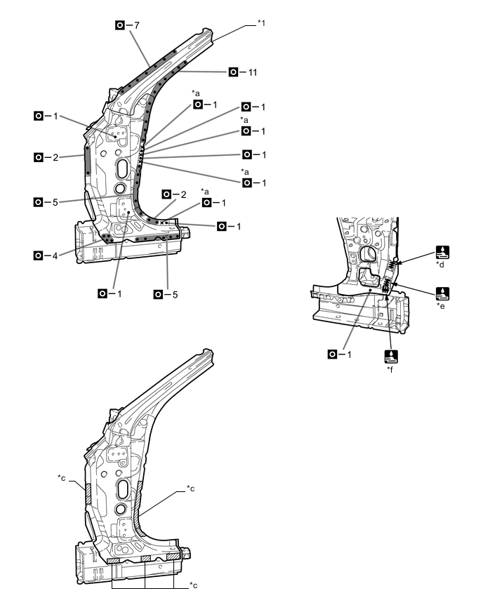
*1 FRONT BODY PILLAR REINFORCE SUB-ASSEMBLY UPPER - - *d 10 mm (0.39 in.) *e 20 mm (0.79 in.) *f 15 mm (0.59 in.) - - Laser Screw Welding - - 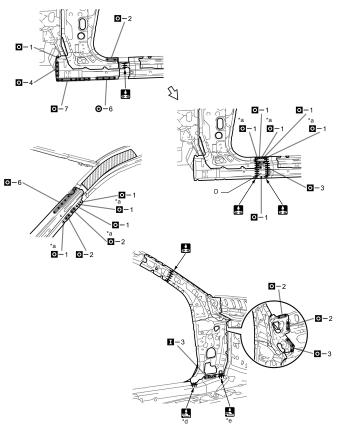
*d 19 mm (0.75 in.) *e 15 mm (0.59 in.) Laser Screw Welding - - 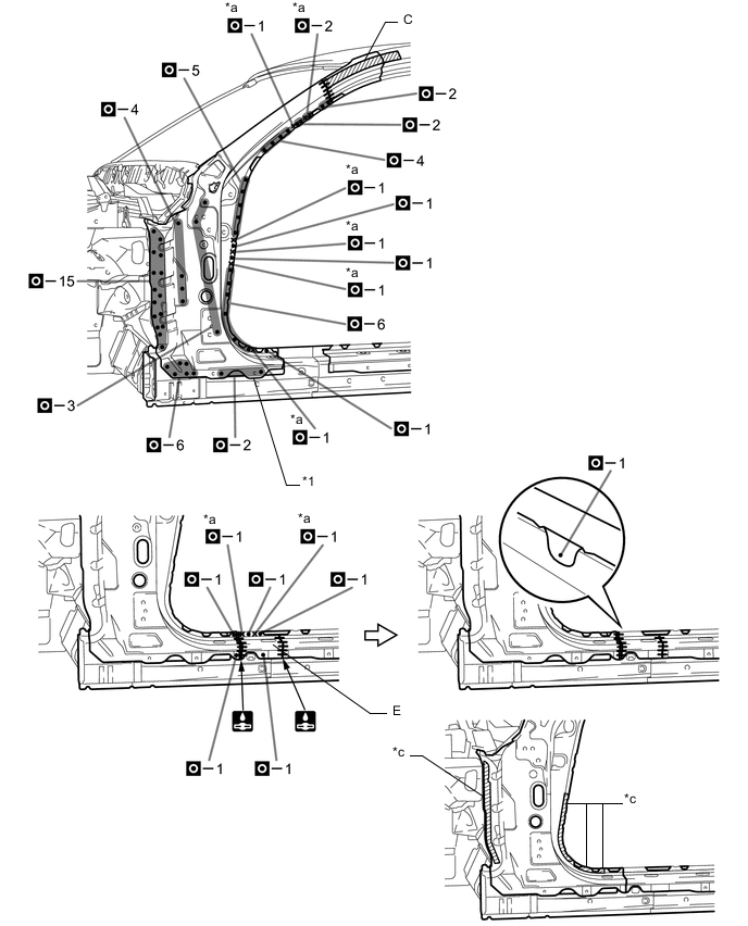
*1 FRONT BODY PILLAR OUTER - - Laser Screw Welding - - 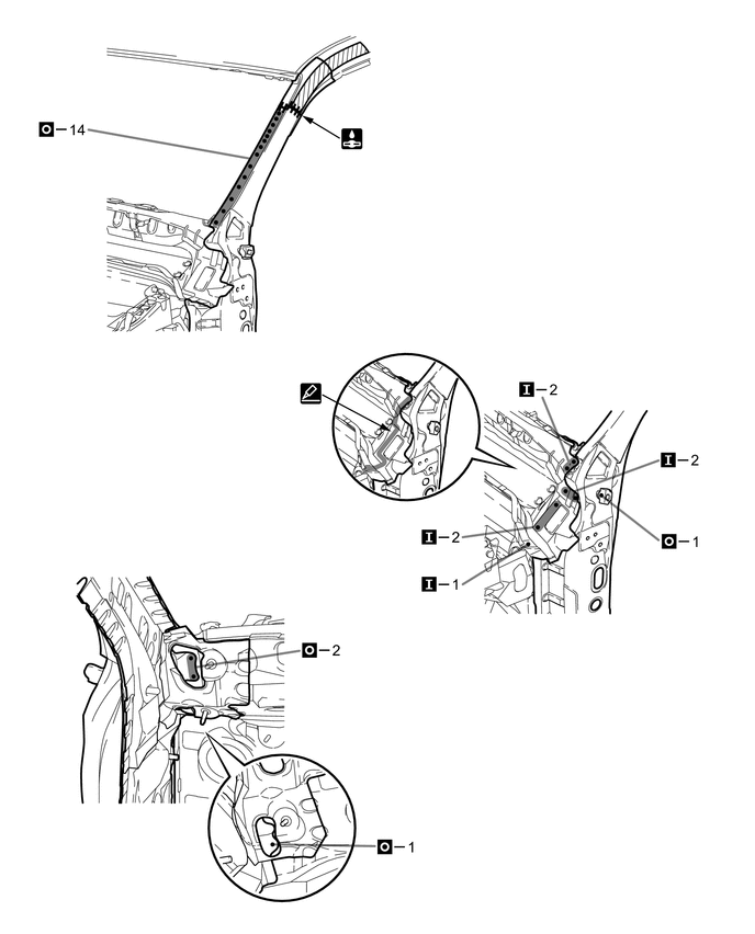
-