FIT STANDARD / ADJUSTMENT METHOD ADJUSTMENT
-
INSPECT HOOD SUB-ASSEMBLY
-
Check that the clearance measurements of areas a through e are within each standard range.
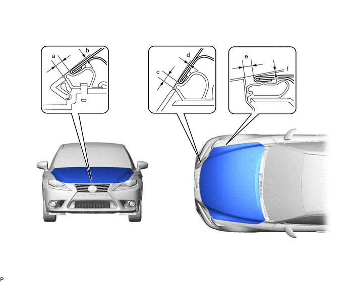
Standard Clearance Area Measurement Area Measurement a 2.95 to 6.95 mm (0.116 to 0.274 in.) b -2.15 to 1.85 mm (-0.0846 to 0.0728 in.) c 2.15 to 6.15 mm (0.0846 to 0.242 in.) d -2.05 to 1.95 mm (-0.0807 to 0.0768 in.) e 2.2 to 5.2 mm (0.0866 to 0.205 in.) f -1.5 to 1.5 mm (-0.0591 to 0.0591 in.)
-
-
ADJUST HOOD SUB-ASSEMBLY
-
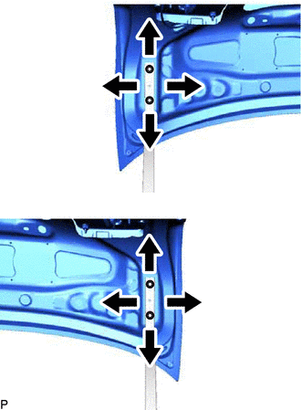
Horizontally and vertically adjust the hood.
-
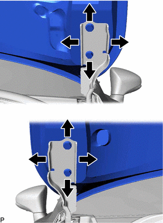
Loosen the 4 hinge bolts of the hood.
-
Adjust the clearance between the hood and front fender by moving the hood.
-
Tighten the 4 hinge bolts after adjustment.
- Torque:
- 13 N*m { 133 kgf*cm, 10 ft.*lbf }
-
-
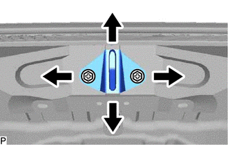
Adjust the height of the front end of the hood using the hood bumper cushions.
-
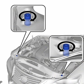
Adjust the 2 hood bumper cushions so that the heights of the hood and fenders are aligned.
Tech Tips
Raise or lower the front end of the hood by turning the 2 hood bumper cushions.
-
-
Adjust the hood lock.
-
Remove the cool air intake duct seal.
-
Remove the hood lock release lever protector.
-
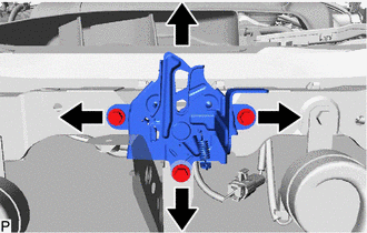
Loosen the 3 bolts.
-
Adjust the hood lock and tighten the 3 bolts.
- Torque:
- 7.5 N*m { 76 kgf*cm, 66 in.*lbf }
-
Check that the striker can engage with the hood lock smoothly.
-
Install the hood lock release lever protector.
-
Install the cool air intake duct seal.
-
-
-
INSPECT FRONT DOOR
-
Check that the clearance measurements of areas a through h are within each standard range.
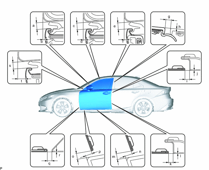
Standard Clearance Area Measurement Area Measurement a 3.35 to 6.35 mm (0.132 to 0.250 in.) b 1.35 to 4.35 mm (0.0531 to 0.171 in.) c 3.35 to 6.35 mm (0.132 to 0.250 in.) d 0.55 to 3.55 mm (0.0217 to 0.140 in.) e 3.35 to 6.35 mm (0.132 to 0.250 in.) f 0.55 to 3.55 mm (0.0217 to 0.140 in.) g 2.5 to 6.5 mm (0.0984 to 0.256 in.) h -2.0 to 2.0 mm (-0.0787 to 0.0787 in.) i 2.6 to 5.0 mm (0.102 to 0.197 in.) j -1.2 to 1.2 mm (-0.0472 to 0.0472 in.) k 2.6 to 5.0 mm (0.102 to 0.197 in.) l -1.2 to 1.2 mm (-0.0472 to 0.0472 in.) m 3.15 to 7.15 mm (0.124 to 0.281 in.) n 5.15 to 9.15 mm (0.203 to 0.360 in.) o 3.15 to 7.15 mm (0.124 to 0.281 in.) p 4.55 to 8.55 mm (0.179 to 0.337 in.) q 2.3 to 5.3 mm (0.0906 to 0.209 in.) r -1.5 to 1.5 mm (-0.0591 to 0.0591 in.) s 3.35 to 6.35 mm (0.132 to 0.250 in.) t 4.55 to 7.55 mm (0.179 to 0.297 in.)
-
-
ADJUST FRONT DOOR
Note
Make sure to turn the engine switch off when adjusting door lock strikers.
-
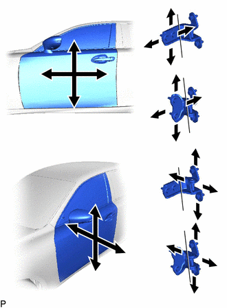
Using SST, loosen the hinge bolts on the vehicle body and adjust the door position.
- SST
- 09812-00020
-
Tighten the hinge bolts on the vehicle body after adjustment.
- Torque:
- 26 N*m { 265 kgf*cm, 19 ft.*lbf }
-
Loosen the hinge bolts on the door and adjust the door position.
-
Tighten the hinge bolts on the door after adjustment.
- Torque:
- 27 N*m { 275 kgf*cm, 20 ft.*lbf }
-
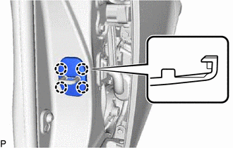
Disengage the 4 claws and remove the front door lock striker cover.
-
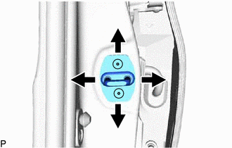
Using a T40 "TORX" socket wrench, slightly loosen the striker mounting screws.
-
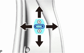
Using a brass bar and a hammer, hit the striker to adjust its position.
-
Using a T40 "TORX" socket wrench, tighten the striker mounting screws after adjustment.
- Torque:
- 23 N*m { 235 kgf*cm, 17 ft.*lbf }
-
Engage the 4 claws to install the front door lock striker cover.
-
-
INSPECT REAR DOOR
-
Check that the clearance measurements of areas a through t are within each standard range.
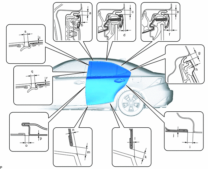
Standard Clearance Area Measurement Area Measurement a 3.45 to 6.45 mm (0.136 to 0.254 in.) b 0.65 to 3.65 mm (0.0256 to 0.144 in.) c 3.45 to 6.45 mm (0.136 to 0.254 in.) d 0.85 to 3.85 mm (0.0335 to 0.152 in.) e 3.35 to 6.35 mm (0.132 to 0.250 in.) f 1.85 to 4.85 mm (0.0728 to 0.191 in.) g 3.35 to 6.35 mm (0.132 to 0.250 in.) h 1.45 to 4.45 mm (0.0571 to 0.175 in.) i 2.3 to 5.3 mm (0.0906 to 0.209 in.) j -1.5 to 1.5 mm (-0.0591 to 0.0591 in.) k 3.15 to 7.15 mm (0.124 to 0.281 in.) l -0.85 to 3.15 mm (-0.0335 to 0.124 in.) m 3.15 to 7.15 mm (0.124 to 0.281 in.) n 0.15 to 4.15 mm (0.00591 to 0.163 in.) o 2.6 to 5.0 mm (0.102 to 0.197 in.) p -1.2 to 1.2 mm (-0.0472 to 0.0472 in.) q 2.5 to 6.5 mm (0.0984 to 0.256 in.) r -2.0 to 2.0 mm (-0.0787 to 0.0787 in.) s 2.5 to 6.5 mm (0.0984 to 0.256 in.) t -2.0 to 2.0 mm (-0.0787 to 0.0787 in.)
-
-
ADJUST REAR DOOR
Note
Make sure to turn the engine switch off when adjusting door lock strikers.
-
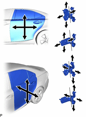
Using SST, loosen the hinge bolts on the vehicle body and adjust the door position.
- SST
- 09812-00020
-
Tighten the hinge bolts on the vehicle body after adjustment.
- Torque:
- 26 N*m { 265 kgf*cm, 19 ft.*lbf }
-
Loosen the hinge bolts on the door and adjust the door position.
-
Tighten the hinge bolts on the door after adjustment.
- Torque:
- 27 N*m { 275 kgf*cm, 20 ft.*lbf }
-
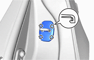
Disengage the 4 claws and remove the rear door lock striker cover.
-
Using a T40 "TORX" socket wrench, slightly loosen the striker mounting screws.
-
Using a brass bar and a hammer, hit the striker to adjust its position.
-
Using a T40 "TORX" socket wrench, tighten the striker mounting screws after adjustment.
- Torque:
- 23 N*m { 235 kgf*cm, 17 ft.*lbf }
-
Engage the 4 claws to install the rear door lock striker cover.
-
-
INSPECT LUGGAGE COMPARTMENT DOOR
-
Check that the clearance measurements of areas a through d are within each standard range.
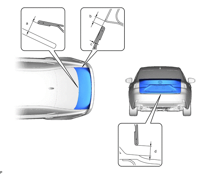
Standard Clearance Area Measurement Area Measurement a 7.6 mm (0.299 in.) b 2.0 to 5.0 mm (0.0787 to 0.197 in.) c -1.7 to 1.3 mm (-0.0669 to 0.0512 in.) d 3.85 to 7.85 mm (0.152 to 0.309 in.)
-
-
ADJUST LUGGAGE COMPARTMENT DOOR
-
Loosen the door side hinge bolts to adjust the door horizontally and vertically.
- Torque:
- 7.5 N*m { 76 kgf*cm, 66 in.*lbf }
-
Using a T40 "TORX" socket wrench, slightly loosen the striker mounting screws.
-
Using a brass bar and a hammer, hit the striker to adjust its position.
-
Using a T40 "TORX" socket wrench, tighten the striker mounting screws after adjustment.
- Torque:
- 23 N*m { 235 kgf*cm, 17 ft.*lbf }
-