FRONT SUSPENSION CROSSMEMBER TWO-DIMENSIONAL DISTANCE
Tech Tips
-
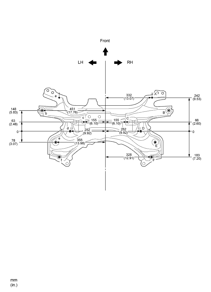
Length measurements are indicated at the points where the arrows extending from the zero point intersect the lines that extend towards the outside of the illustration from each point.
-
Point C, c, on the vehicle are asymmetrical.
-
In cases in which only one dimension is given, left and right are symmetrical.
-
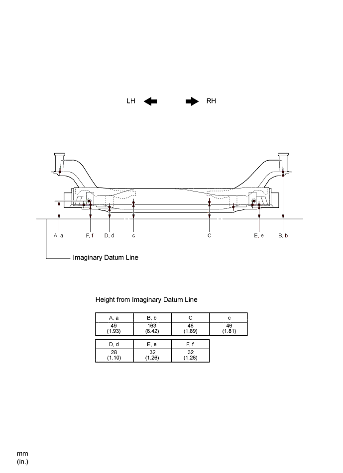
For symbols, capital letters indicate right side of vehicle, small letters indicate left side of vehicle (seen from rear).
| Symbol | Name | Hole Diameter mm (in.) |
|---|---|---|
| A, a | Front Suspension Lower Arm Installation Hole | φ17.5 (0.69) |
| B, b | Front Suspension Crossmember Installation Hole | φ22 (0.87) |
| C, c | Front Suspension Crossmember Standard Hole | φ12 (0.47) |
| D, d | Steering Gear Box Installation Hole | φ17 (0.67) |
| E, e | Front Suspension Lower Arm Installation Hole | 21X18.5 (0.83X0.73) |
| F, f | Front Suspension Crossmember Installation Hole | φ22 (0.87) |