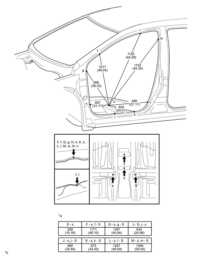
FRONT DOOR THREE-DIMENSIONAL DISTANCE
Tech Tips
-
Use specification T when performing centering measurements for the body dimensions.
-
In cases in which only one dimension is given, left and right are symmetrical.
-
For symbols, capital letters indicate right side of vehicle, small letters indicate left side of vehicle (seen from rear).
| Symbol | Name | Hole Diameter mm (in.) |
|---|---|---|
| A, a | Roof Panel Corner | - |
| B | Roof Window Glass Installation Hole | 20.5X16.5 (0.81X0.65) |
| b | Roof Window Glass Installation Hole | φ16.5 (0.65) |
| C, c | Hood Hinge Installation Nut | M8 (0.31) |
| D, d | Front Door Hinge Installation Nut | M8 (0.31) |
| E, e | Front Door Hinge Installation Nut | M8 (0.31) |
| F, f | Front Body Pillar Assembly Mark | - |
| G, g | Front Body Pillar Assembly Mark | - |
| H, h | Front Body Pillar Assembly Mark | - |
| J, j | Rocker Panel Assembly Mark | - |
| K, k | Rocker Panel Assembly Mark | - |
| L, l | Roof Side Rail Assembly Mark | - |
| M, m | Center Body Pillar Assembly Mark | - |
| N, n | Center Body Pillar Assembly Mark | - |
| O, o | Front Door Lock Striker Installation Nut | M8 (0.31) |
| P, p | Rear Door Hinge Installation Nut | M8 (0.31) |
| Q, q | Rear Door Hinge Installation Nut | M8 (0.31) |
| R, r | Rocker Panel Assembly Mark | - |
| S, s | Front Floor Crossmember Standard Hole | 14X11 (0.55X0.43) |
| T | Front Floor Center Panel Standard Hole | φ13 (0.51) |
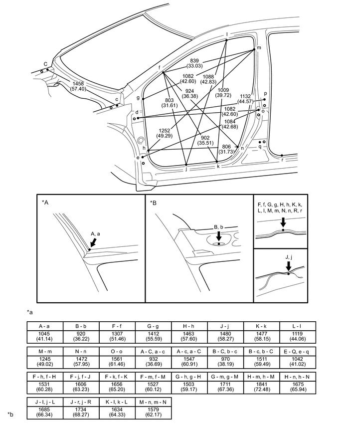
| *A | for Standard Roof | *B | for Glass Roof |
| *a | Distance between points other than those above | *b | mm (in.) |
| *a | Distance between points other than those above | *b | mm (in.) |