FIT STANDARD / ADJUSTMENT METHOD ADJUSTMENT
-
INSPECT HOOD SUB-ASSEMBLY
-
Check that the clearance measurements of areas "a" through "d" are within each standard range.
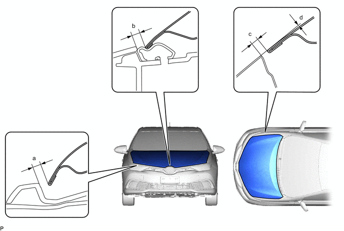
Standard Clearance Area Measurement Area Measurement a 3.0 to 7.0 mm (0.118 to 0.276 in.) b 3.0 to 7.0 mm (0.118 to 0.276 in.) c 2.0 to 5.0 mm (0.0787 to 0.197 in.) d -1.5 to 1.5 mm (-0.0591 to 0.0591 in.) Tech Tips
Centering bolts are used to mount the hood hinge and hood lock. The hood and hood lock cannot be adjusted with the centering bolts installed. Substitute the centering bolts with standard bolts when making adjustments.
-
-
ADJUST HOOD SUB-ASSEMBLY
-
Horizontally and vertically adjust the hood.
-
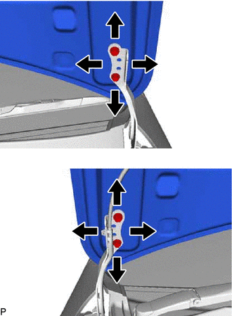
Loosen the hinge bolts of the hood.
-
Adjust the clearance between the hood and front fender by moving the hood.
-
Tighten the hinge bolts after the adjustment.
- Torque:
- 13 N*m { 133 kgf*cm, 10 ft.*lbf }
-
-
Adjust the height of the front end of the hood using the hood bumper cushions.
-
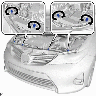
Adjust the hood bumper cushions so that the heights of the hood and fender are aligned.
Tech Tips
Raise or lower the front end of the hood by turning the hood bumper cushions.
-
-
Adjust the hood lock.
-
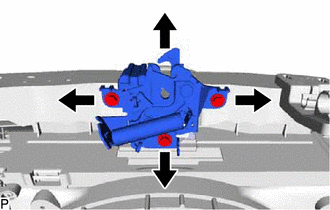
Loosen the 3 bolts.
-
Tighten the bolts after adjustment.
- Torque:
- 7.5 N*m { 76 kgf*cm, 66 in.*lbf }
-
Check that the striker can engage with the hood lock smoothly.
-
-
-
INSPECT FRONT DOOR
-
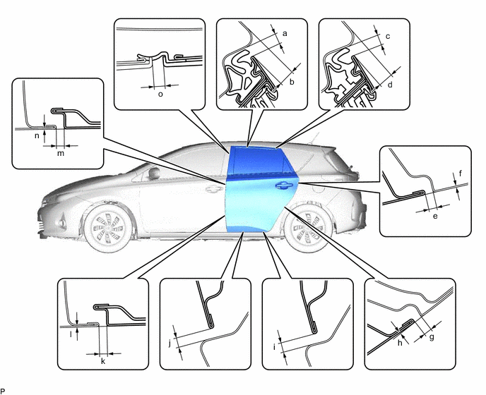
Check that the clearance measurements of areas "a" through "o" are within each standard range.
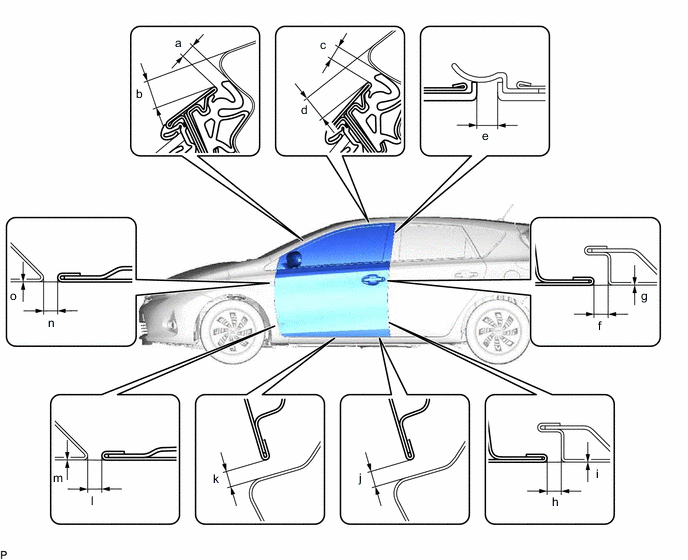
Standard Clearance Area Measurement Area Measurement a 3.9 to 6.9 mm (0.154 to 0.272 in.) b 9.7 to 12.7 mm (0.382 to 0.500 in.) c 3.9 to 6.9 mm (0.154 to 0.272 in.) d 8.9 to 11.9 mm (0.350 to 0.469 in.) e 3.0 to 7.0 mm (0.118 to 0.276 in.) f 3.2 to 5.6 mm (0.126 to 0.220 in.) g -1.2 to 1.2 mm (-0.0472 to 0.0472 in.) h 3.2 to 5.6 mm (0.126 to 0.220 in.) i -1.2 to 1.2 mm (-0.0472 to 0.0472 in.) j 4.2 to 7.2 mm (0.165 to 0.283 in.) k 4.2 to 7.2 mm (0.165 to 0.283 in.) l 2.7 to 5.7 mm (0.106 to 0.224 in.) m -1.5 to 1.5 mm (-0.0591 to 0.0591 in.) n 2.7 to 5.7 mm (0.106 to 0.224 in.) o -1.5 to 1.5 mm (-0.0591 to 0.0591 in.) - - Tech Tips
-
Use the same procedure for the RH side and LH side.
-
The procedure listed below is for the LH side.
-
Centering bolts are used to mount the door hinge to the vehicle body and door. The door cannot be adjusted with the centering bolts installed. Substitute the centering bolts with standard bolts when making adjustments.
-
-
-
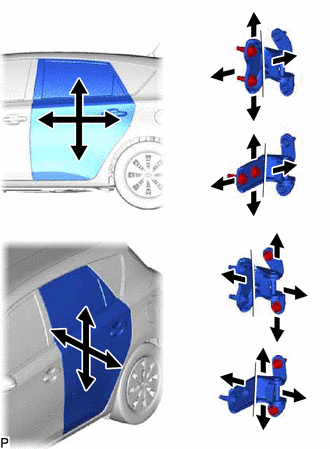
ADJUST FRONT DOOR
Note
Make sure to turn the power switch off when adjusting door lock strikers.
-
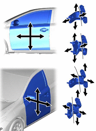
Using SST, loosen the hinge bolts on the vehicle body and adjust the door position.
- SST
- 09812-00010
-
Tighten the hinge bolts on the vehicle body after adjustment.
- Torque:
- 26 N*m { 265 kgf*cm, 19 ft.*lbf }
-
Loosen the hinge bolts on the door and adjust the door position.
-
Tighten the hinge bolts on the door after adjustment.
- Torque:
- 26 N*m { 265 kgf*cm, 19 ft.*lbf }
-
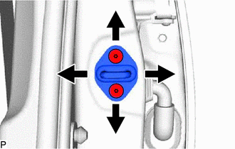
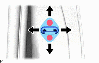
Using a T40 "TORX" socket wrench, slightly loosen the striker mounting screws.
-
Using a brass bar and a hammer, hit the striker to adjust its position.
-
Using a T40 "TORX" socket wrench, tighten the striker mounting screws after adjustment.
- Torque:
- 23 N*m { 235 kgf*cm, 17 ft.*lbf }
-
-
INSPECT REAR DOOR (for Wagon)
-
Check that the clearance measurements of areas "a" through "o" are within each standard range.
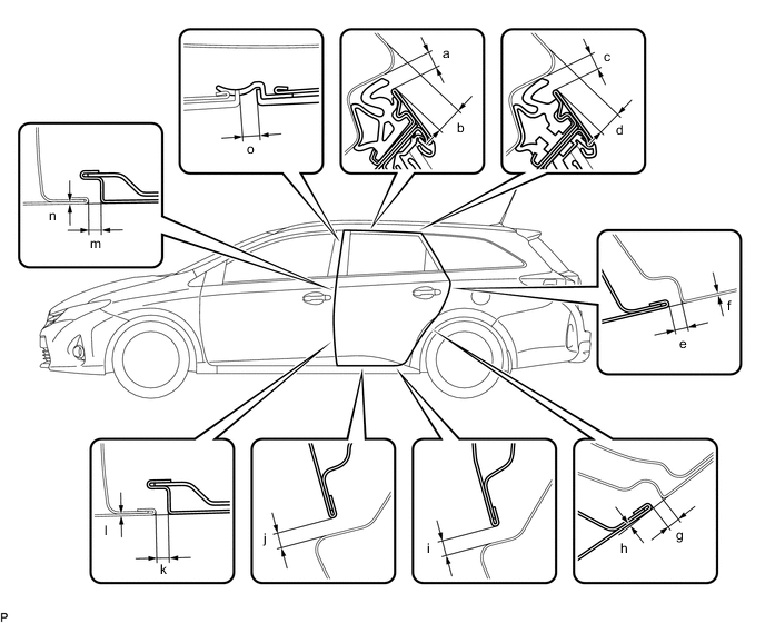
Standard Clearance Area Measurement Area Measurement a 4.05 to 7.05 mm (0.159 to 0.278 in.) b 7.8 to 10.8 mm (0.307 to 0.425 in.) c 4.05 to 7.05 mm (0.159 to 0.278 in.) d 6.5 to 9.5 mm (0.256 to 0.374 in.) e 2.7 to 5.7 mm (0.106 to 0.224 in.) f -1.5 to 1.5 mm (-0.0591 to 0.0591 in.) g 2.7 to 5.7 mm (0.106 to 0.224 in.) h -1.5 to 1.5 mm (-0.0591 to 0.0591 in.) i 4.2 to 7.2 mm (0.165 to 0.283 in.) j 4.2 to 7.2 mm (0.165 to 0.283 in.) k 3.2 to 5.6 mm (0.126 to 0.220 in.) l -1.2 to 1.2 mm (-0.0472 to 0.0472 in.) m 3.2 to 5.6 mm (0.126 to 0.220 in.) n -1.2 to 1.2 mm (-0.0472 to 0.0472 in.) o 3.0 to 7.0 mm (0.118 to 0.276 in.) - -
-
-
INSPECT REAR DOOR (for Hatchback)
-
Check that the clearance measurements of areas "a" through "o" are within each standard range.
Standard Clearance Area Measurement Area Measurement a 3.9 to 6.9 mm (0.154 to 0.272 in.) b 7.5 to 10.5 mm (0.295 to 0.413 in.) c 3.9 to 6.9 mm (0.154 to 0.272 in.) d 6.6 to 9.6 mm (0.260 to 0.378 in.) e 2.7 to 5.7 mm (0.106 to 0.224 in.) f -1.5 to 1.5 mm (-0.0591 to 0.0591 in.) g 2.7 to 5.7 mm (0.106 to 0.224 in.) h -1.5 to 1.5 mm (-0.0591 to 0.0591 in.) i 4.2 to 7.2 mm (0.165 to 0.283 in.) j 4.2 to 7.2 mm (0.165 to 0.283 in.) k 3.2 to 5.6 mm (0.126 to 0.220 in.) l -1.2 to 1.2 mm (-0.0472 to 0.0472 in.) m 3.2 to 5.6 mm (0.126 to 0.220 in.) n -1.2 to 1.2 mm (-0.0472 to 0.0472 in.) o 3.0 to 7.0 mm (0.118 to 0.276 in.) - -
Tech Tips
-
Use the same procedure for the RH side and LH side.
-
The procedure listed below is for the LH side.
-
Centering bolts are used to mount the door hinge to the vehicle body and door. The door cannot be adjusted with the centering bolts installed. Substitute the centering bolts with standard bolts when making adjustments.
-
-
ADJUST REAR DOOR
Note
Make sure to turn the ignition switch off when adjusting door lock strikers.
Tech Tips
Use the same procedure for the hatchback and wagon.
-
Using SST, loosen the hinge bolts on the vehicle body and adjust the door position.
- SST
- 09812-00010
-
Tighten the hinge bolts on the vehicle body after the adjustment.
- Torque:
- 26 N*m { 265 kgf*cm, 19 ft.*lbf }
-
Loosen the hinge bolts on the door and adjust the door position.
-
Tighten the hinge bolts on the door after the adjustment.
- Torque:
- 26 N*m { 265 kgf*cm, 19 ft.*lbf }
-
Using a T40 "TORX" socket wrench, slightly loosen the striker mounting screws.
-
Using a brass bar and a hammer, hit the striker to adjust its position.
-
Using a T40 "TORX" socket wrench, tighten the striker mounting screws after adjustment.
- Torque:
- 23 N*m { 235 kgf*cm, 17 ft.*lbf }
-
-
INSPECT BACK DOOR (for Wagon)
-
Check that the clearance measurements of areas "a" through "h" are within each standard range.
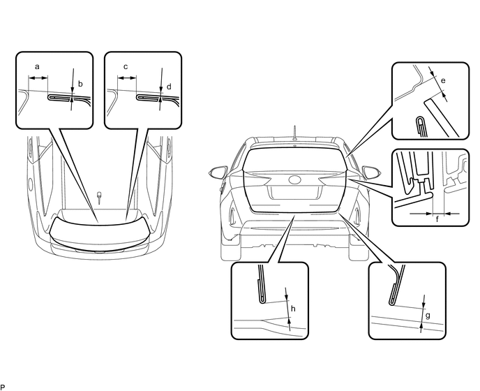
Standard Clearance Area Measurement Area Measurement a 5.5 to 8.5 mm (0.217 to 0.335 in.) b -1.5 to 1.5 mm (-0.0591 to 0.0591 in.) c 5.5 to 8.5 mm (0.217 to 0.335 in.) d -1.5 to 1.5 mm (-0.0591 to 0.0591 in.) e 3.85 to 6.85 mm (0.152 to 0.270 in.) f 3.5 to 7.5 mm (0.138 to 0.295 in.) g 4.35 to 7.35 mm (0.171 to 0.289 in.) h 4.35 to 7.35 mm (0.171 to 0.289 in.) Tech Tips
Centering bolts are used to mount the door hinge to the vehicle body and door. The door cannot be adjusted with the centering bolts installed. Substitute the centering bolts with standard bolts (with washers) when making adjustments.
-
-
ADJUST BACK DOOR (for Wagon)
-
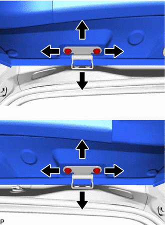
Before adjusting the upper end of the back door up and down or left and right, loosen the bolts.
-
Tighten the body side hinge after adjustment.
- Torque:
- 19.5 N*m { 199 kgf*cm, 14 ft.*lbf }
-
Using a T40 "TORX" socket wrench, slightly loosen the striker mounting screws.
-
Using a brass bar and a hammer, hit the striker to adjust its position.
-
Using a T40 "TORX" socket wrench, tighten the striker mounting screws after adjustment.
- Torque:
- 11.5 N*m { 117 kgf*cm, 8 ft.*lbf }
-
-
INSPECT BACK DOOR (for Hatchback)
-
Check that the clearance measurements of areas "a" through "h" are within each standard range.
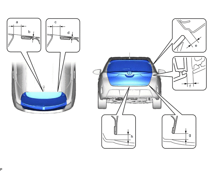
Standard Clearance Area Measurement Area Measurement a 5.5 to 8.5 mm (0.217 to 0.335 in.) b 0.5 to 2.0 mm (0.0197 to 0.0787 in.) c 5.5 to 8.5 mm (0.217 to 0.335 in.) d 0.5 to 2.0 mm (0.0197 to 0.0787 in.) e 3.85 to 6.85 mm (0.152 to 0.270 in.) f 3.5 to 7.5 mm (0.138 to 0.295 in.) g 4.35 to 7.35 mm (0.171 to 0.289 in.) h 4.35 to 7.35 mm (0.171 to 0.289 in.) Tech Tips
-
Use the same procedure for the RH side and LH side.
-
The following procedure is for the LH side.
-
Centering bolts are used to mount the door hinge to the vehicle body and door. The door cannot be adjusted with the centering bolts installed. Substitute the centering bolts with standard bolts (with washers) when making adjustments.
-
-
-
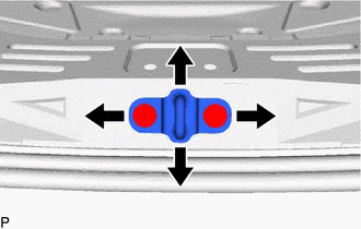
ADJUST BACK DOOR (for Hatchback)
-
Before adjusting the upper end of the back door up and down or left and right, loosen the bolts.
-
Tighten the body side hinge after adjustment.
- Torque:
- 19.5 N*m { 199 kgf*cm, 14 ft.*lbf }
-
Using a T40 "TORX" socket wrench, slightly loosen the striker mounting screws.
-
Using a brass bar and a hammer, hit the striker to adjust its position.
-
Using a T40 "TORX" socket wrench, tighten the striker mounting screws after adjustment.
- Torque:
- 11.5 N*m { 117 kgf*cm, 8 ft.*lbf }
-