UNDER BODY(for Hatchback) TWO-DIMENSIONAL DISTANCE
-
for Torsion Beam Type Suspension
Tech Tips
-
Point B, b and C, c on the vehicle are asymmetrical.
-
Length measurements are indicated at the points where the arrows extending from the zero point intersect the lines that extend towards the outside of the illustration from each point.
-
In cases in which only one dimension is given, left and right are symmetrical.
-
For symbols, capital letters indicate right side of vehicle, small letters indicate left side of vehicle (seen from rear).
Measuring Point Name Symbol Name Hole Diameter
mm (in.)
A, a Front Body Mounting Reinforcement Standard Hole φ10 (0.39) B, b Front Crossmember Installation Nut M12 (0.47) C, c Front Side Member Standard Hole φ18 (0.71) D, d Front Suspension Crossmember Installation Nut M14 (0.55) E, e Front Suspension Installation Hole φ12.5 (0.49) F, f Front Suspension Crossmember Installation Nut M14 (0.55) G, g Torque Front Box Standard Hole φ25 (0.98) H, h Front Side Rear Member Standard Hole φ22 (0.87) J, j Front Side Inner Rear Member Standard Hole φ18 (0.71) K, k Front Floor Pan Standard Hole φ18 (0.71) L, l Rear Floor Side Member Standard Hole φ25 (0.98) M, m Trailing Arm Installation Hole φ15 (0.59) N, n Rear Spring Plate Standard Hole φ10 (0.39) O, o Rear Shock Absorber Installation Hole φ24.5 (0.96) P, p Rear Floor Side Member Standard Hole φ16 (0.63) Q, q Towing Hitch Installation Nut M12 (0.47) Wheel Base Wheel Base 2600 mm (102.36 in.) 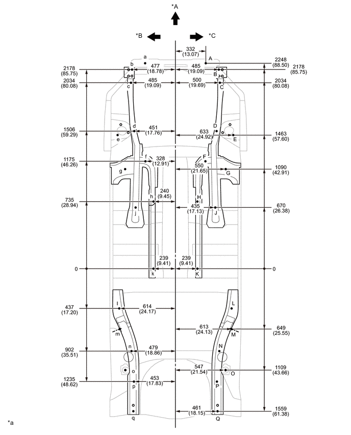
*A Front *B LH *C RH - - *a mm
(in.)
- - 
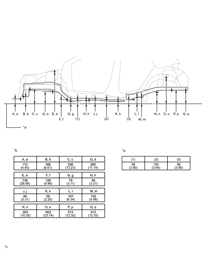
*a Imaginary Datum Line *b Height from Imaginary Datum Line *c mm
(in.)
- - -
-
for Double Wishbone Type Suspension
Tech Tips
-
Point B, b and C, c on the vehicle are asymmetrical.
-
Length measurements are indicated at the points where the arrows extending from the zero point intersect the lines that extend towards the outside of the illustration from each point.
-
In cases in which only one dimension is given, left and right are symmetrical.
-
For symbols, capital letters indicate right side of vehicle, small letters indicate left side of vehicle (seen from rear).
Measuring Point Name Symbol Name Hole Diameter
mm (in.)
A, a Front Body Mounting Reinforcement Standard Hole φ10 (0.39) B, b Front Crossmember Installation Nut M12 (0.47) C, c Front Side Member Standard Hole φ18 (0.71) D, d Front Suspension Crossmember Installation Nut M14 (0.55) E, e Front Suspension Installation Hole φ12.5 (0.49) F, f Front Suspension Crossmember Installation Nut M14 (0.55) G, g Torque Front Box Standard Hole φ25 (0.98) H, h Front Side Rear Member Standard Hole φ22 (0.87) J, j Front Side Inner Rear Member Standard Hole φ18 (0.71) K, k Front Floor Pan Standard Hole φ18 (0.71) L, l Rear Floor Side Member Standard Hole φ25 (0.98) M, m Trailing Arm Bracket Installation Nut M12 (0.47) N, n Rear Suspension Member Installation Nut M14 (0.55) O, o Rear Shock Absorber Installation Hole φ24.5 (0.96) P, p Rear Floor Side Member Standard Hole φ16 (0.63) Q, q Towing Hitch Installation Nut M12 (0.47) Wheel Base Wheel Base 2600 mm (102.36 in.) 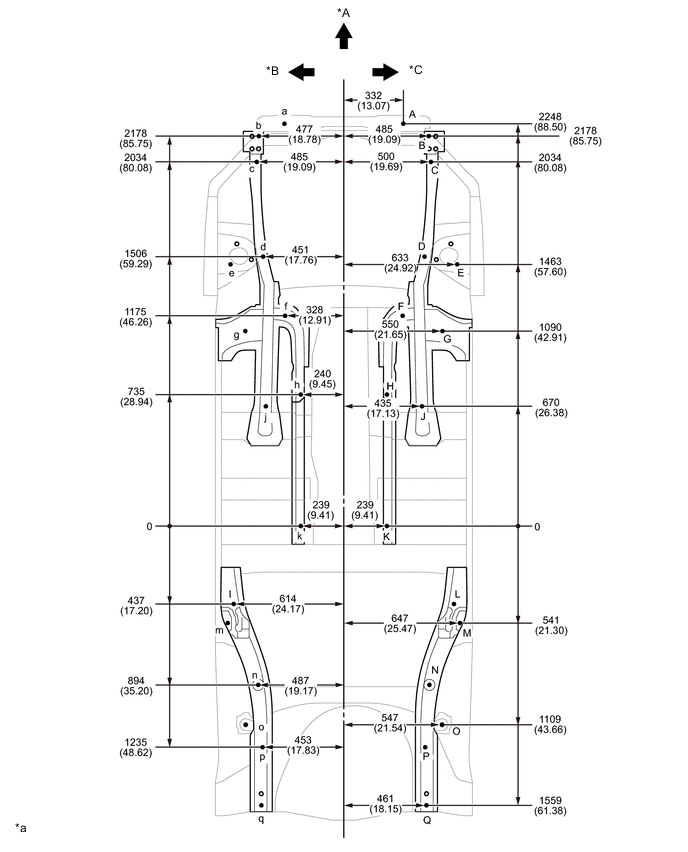
*A Front *B LH *C RH - - *a mm
(in.)
- - 
*a Imaginary Datum Line *b Height from Imaginary Datum Line *c mm
(in.)
- - -