REAR FLOOR PAN(for Wagon) ASSEMBLY REPLACEMENT
-
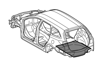
With the body lower back panel removed.
-
REMOVAL
Symbol Meaning 
Remove Weld Points
-
After removing the rear floor side panel sub-assembly, remove the rear floor pan.
REMOVAL POINT
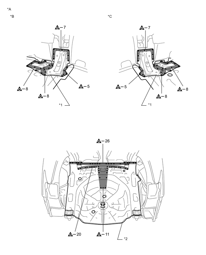
*A for Torsion Beam Type Suspension *B LH *C RH - - *1 REAR FLOOR SIDE PANEL SUB-ASSEMBLY *2 REAR FLOOR PAN 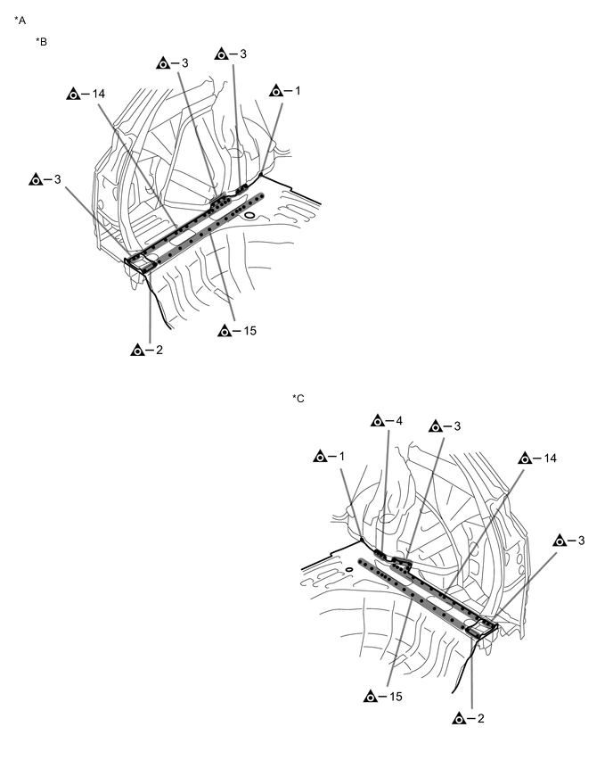
*A for Torsion Beam Type Suspension *B LH Side *C RH Side - - 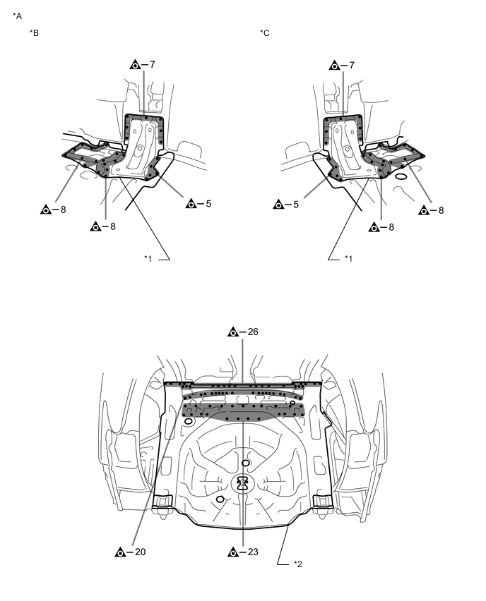
*A for Double Wishbone Type Suspension *B LH *C RH - - *1 REAR FLOOR SIDE PANEL SUB-ASSEMBLY *2 REAR FLOOR PAN 
*A for Double Wishbone Type Suspension *B LH Side *C RH Side - - -
-
INSTALLATION
Symbol Meaning 
Plug Weld 
Fillet Weld
-
Temporarily install the new parts and measure each part of the new parts in accordance with the body dimension diagram. (See the body dimensions)
-
Before temporarily installing the new parts, weld the rear floor pan, spare wheel carrier bracket, rear floor pan reinforcement and weld bolts with the standard number of welding points.
-
After welding the rear floor pan to the vehicle side, install the rear floor side panel sub-assembly.
-
After welding, apply body sealer and undercoating to the corresponding parts. (See the painting/coating)
-
After applying the top coat, apply anti-rust agent to the internal panel portion of the closed section structural weld points.
INSTALLATION POINT(w/o Deck Floor Box)
-
Temporarily install the new parts and measure each part of the new parts in accordance with the body dimension diagram. (See the body dimensions)
-
Before temporarily installing the new parts, weld the rear floor pan, spare wheel carrier bracket, rear floor pan reinforcement, weld studs and weld bolts with the standard number of welding points.
-
After welding the rear floor pan to the vehicle side, install the rear floor side panel sub-assembly.
-
After welding, apply body sealer and undercoating to the corresponding parts. (See the painting/coating)
-
After applying the top coat, apply anti-rust agent to the internal panel portion of the closed section structural weld points.
INSTALLATION POINT(w/ Deck Floor Box)
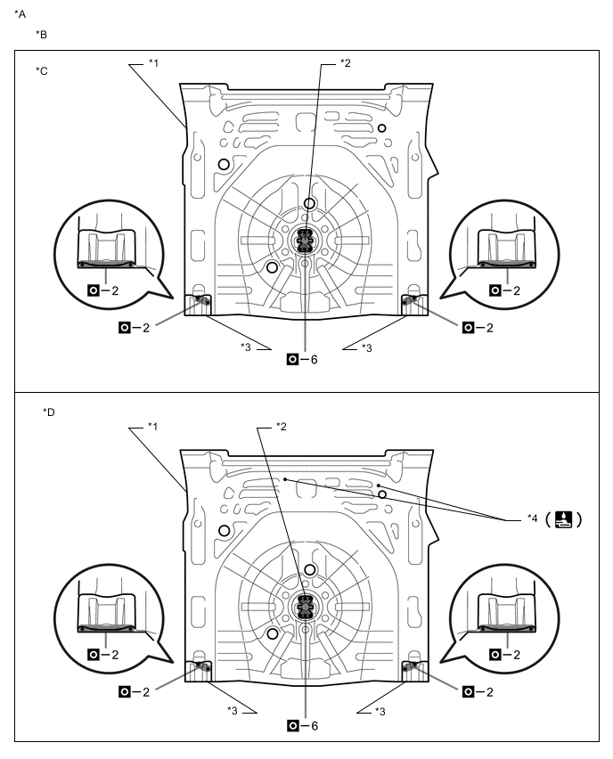
*A for Torsion Beam Type Suspension *B Upper Face *C w/o Deck Floor Box *D w/ Deck Floor Box *1 REAR FLOOR PAN *2 SPARE WHEEL CARRIER BRACKET *3 REAR FLOOR PAN REINFORCEMENT *4 WELD STUDS 
*A for Torsion Beam Type Suspension *B Lower Face *1 WELD BOLTS - - 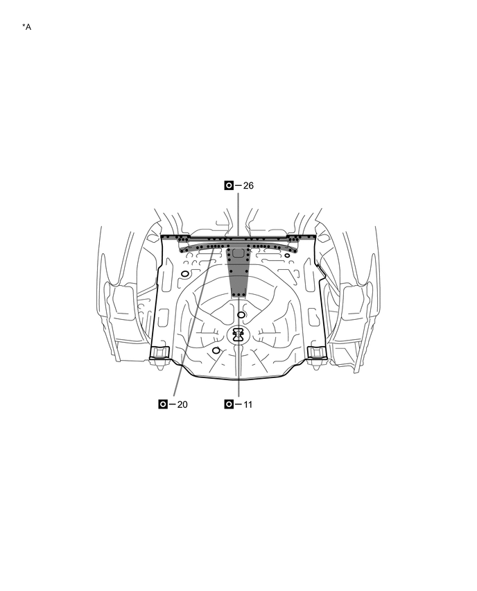
*A for Torsion Beam Type Suspension - - 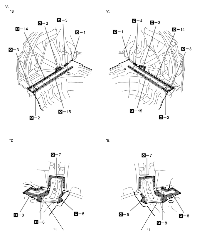
*A for Torsion Beam Type Suspension *B LH Side *C RH Side *D LH *E RH - - *1 REAR FLOOR SIDE PANEL SUB-ASSEMBLY - - 
*A for Double Wishbone Type Suspension *B Upper Face *C w/o Deck Floor Box *D w/ Deck Floor Box *1 REAR FLOOR PAN *2 SPARE WHEEL CARRIER BRACKET *3 REAR FLOOR PAN REINFORCEMENT *4 WELD STUDS 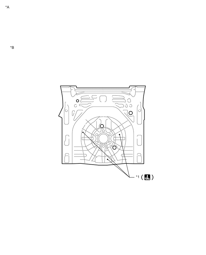
*A for Double Wishbone Type Suspension *B Lower Face *1 WELD BOLTS - - 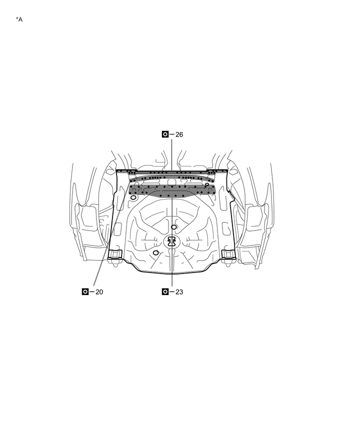
*A for Double Wishbone Type Suspension - - 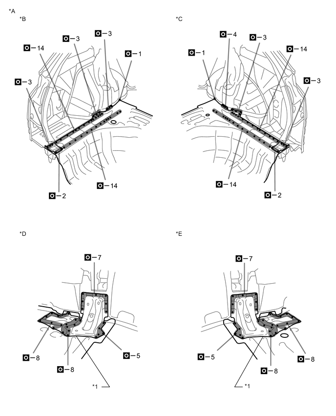
*A for Double Wishbone Type Suspension *B LH Side *C RH Side *D LH *E RH - - *1 REAR FLOOR SIDE PANEL SUB-ASSEMBLY - - -