REAR FLOOR LOWER FRONT CROSSMEMBER(for Wagon) ASSEMBLY REPLACEMENT
-
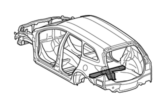
With the rear floor pan removed.
-
REMOVAL
Symbol Meaning 
Remove Weld Points 
Remove Weld Points 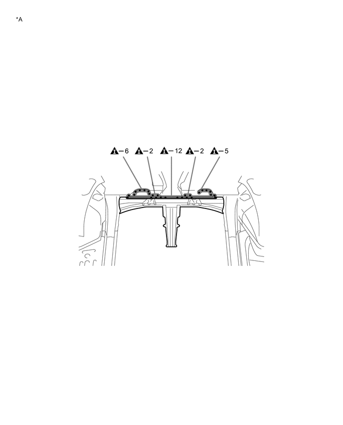
*A for Torsion Beam Type Suspension - - 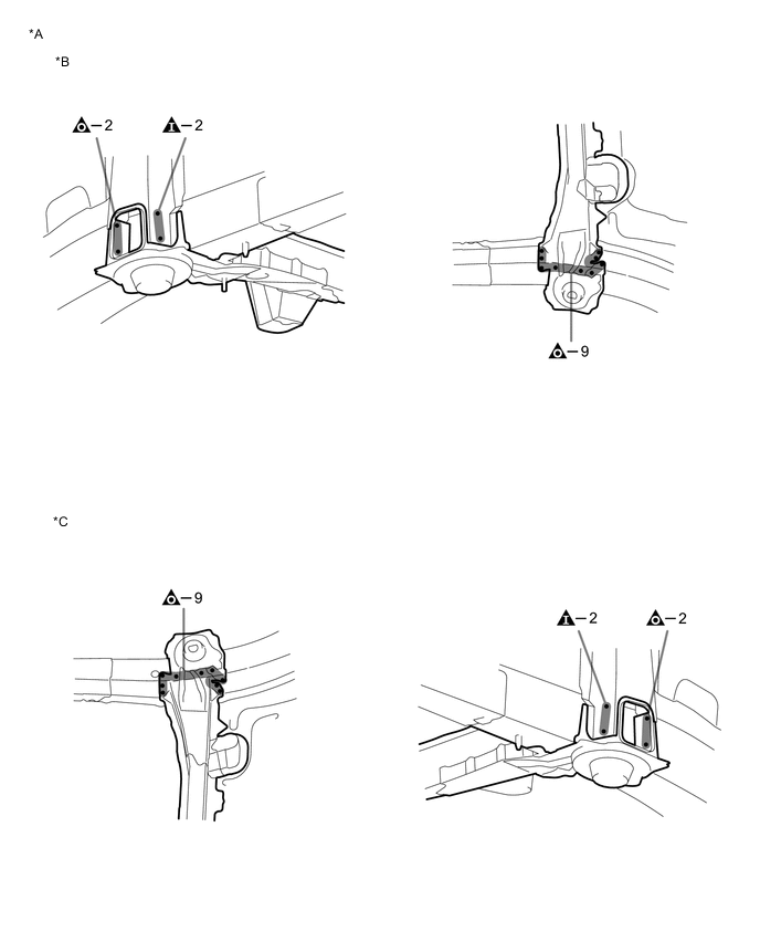
*A for Torsion Beam Type Suspension *B LH Side *C RH Side - - 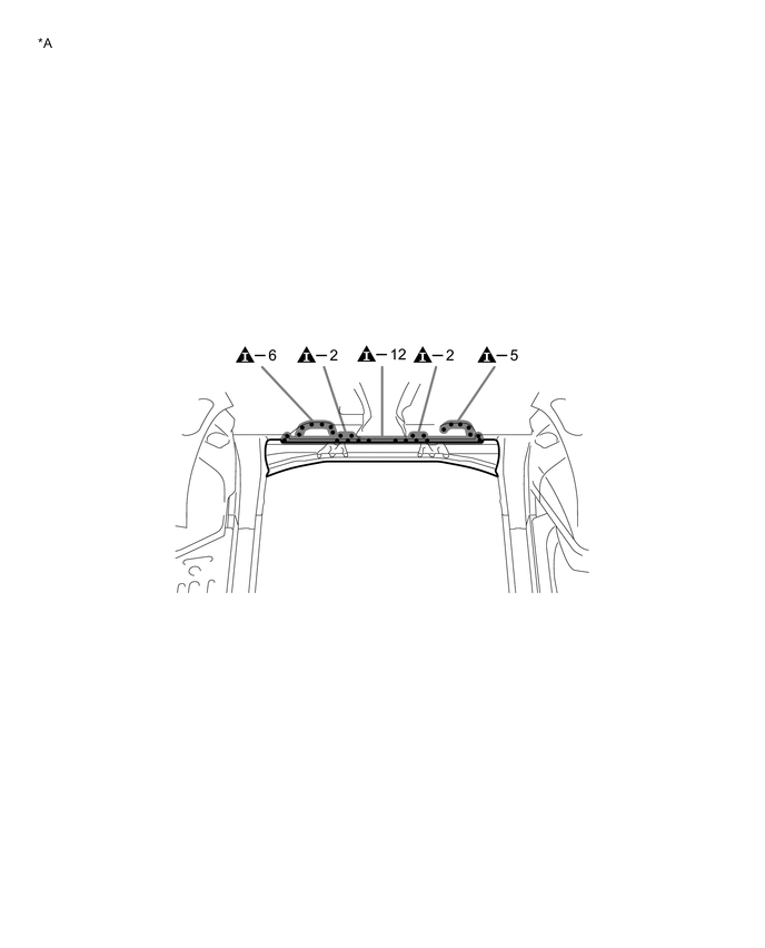
*A for Double Wishbone Type Suspension - - 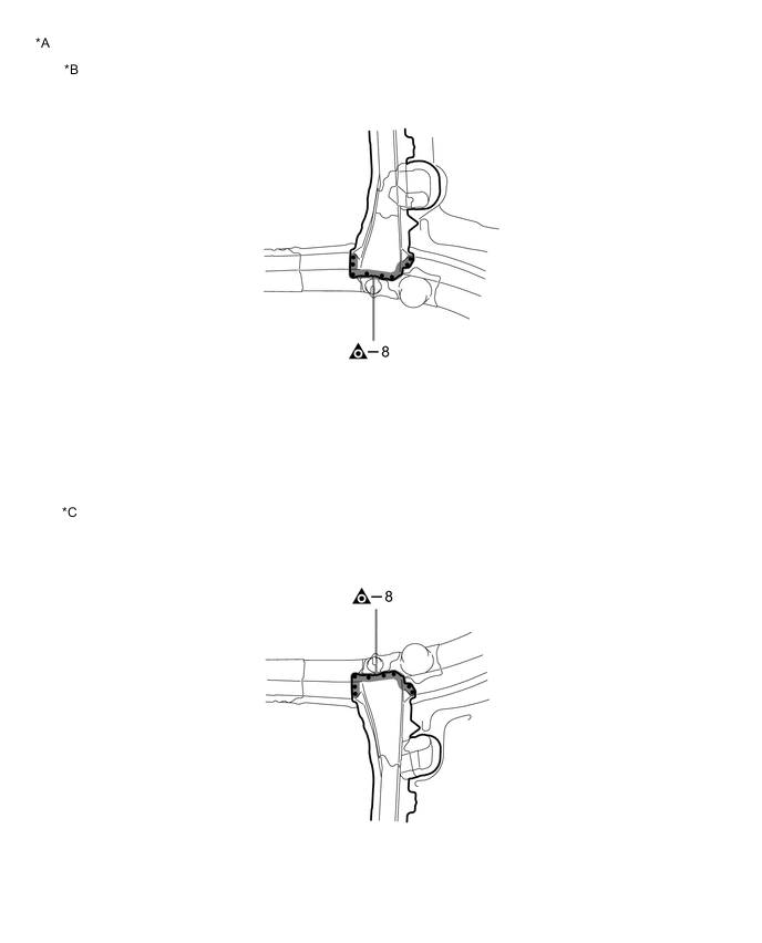
*A for Double Wishbone Type Suspension *B LH Side *C RH Side - - -
INSTALLATION
Symbol Meaning 
Plug Weld 
Plug Weld
-
Temporarily install the new parts and measure each part of the new parts in accordance with the body dimension diagram. (See the body dimensions)
-
After welding, apply undercoating to the corresponding parts. (See the painting/coating)
-
After applying the top coat, apply anti-rust agent to the internal panel portion of the closed section structural weld points.
INSTALLATION POINT(for Torsion Beam Type Suspension)
-
After welding, apply undercoating to the corresponding parts. (See the painting/coating)
-
After applying the top coat, apply anti-rust agent to the internal panel portion of the closed section structural weld points.
INSTALLATION POINT(for Double Wishbone Type Suspension)
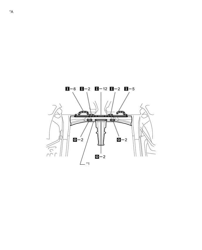
*A for Torsion Beam Type Suspension - - *1 REAR FLOOR CROSS MEMBER SUB-ASSEMBLY NO.2 - - 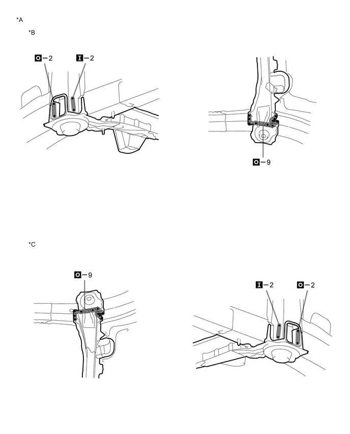
*A for Torsion Beam Type Suspension *B LH Side *C RH Side - - 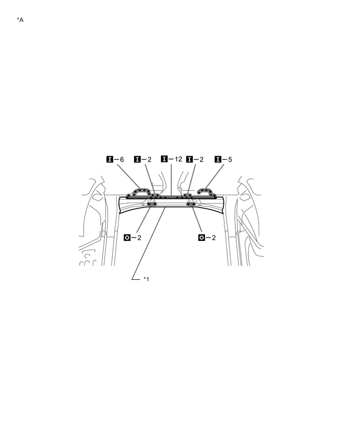
*A for Double Wishbone Type Suspension - - *1 REAR FLOOR CROSS MEMBER SUB-ASSEMBLY NO.2 - - 
*A for Double Wishbone Type Suspension *B LH Side *C RH Side - - -