FIT STANDARD / ADJUSTMENT METHOD ADJUSTMENT
-
INSPECT HOOD SUB-ASSEMBLY (for TMMK Made)
-
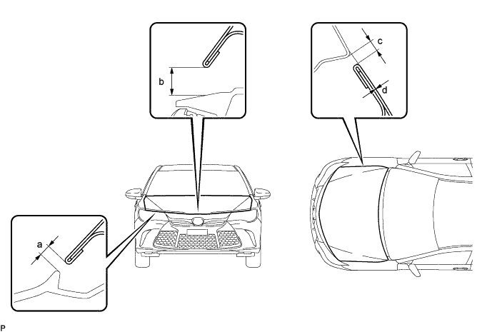
Check that the clearance measurements of areas a through d are within each standard range.
Reference Value Area Measurement Area Measurement a 5.5 to 9.5 mm (0.217 to 0.374 in.) b 7.15 to 11.15 mm (0.281 to 0.439 in.) c 2.0 to 5.0 mm (0.0787 to 0.197 in.) d -1.5 to 1.5 mm (-0.0591 to 0.0591 in.) Tech Tips
Centering bolts are used to mount the hood hinge and hood lock. The hood and hood lock cannot be adjusted with the centering bolts installed. Substitute the centering bolts with standard bolts when making adjustments.
-
-
ADJUST HOOD SUB-ASSEMBLY (for TMMK Made)
-
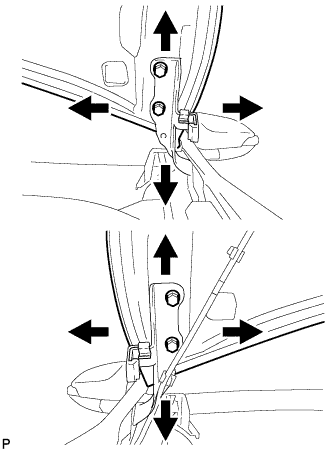
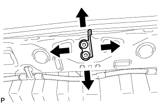
Horizontally and vertically adjust the hood.
-
Loosen the 4 hinge bolts of the hood.
-
Adjust the clearance between the hood and front fender by moving the hood.
-
Tighten the 4 hinge bolts after the adjustment.
- Torque:
- 13 N*m { 133 kgf*cm, 10 ft.*lbf }
-
-
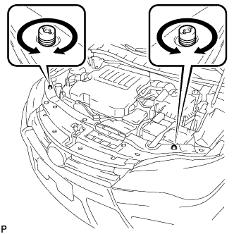
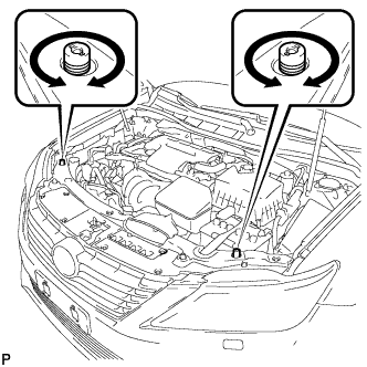
Adjust the height of the front end of the hood using the cushion rubbers.
-
Adjust the 2 cushion rubbers so that the heights of the hood and fender are aligned.
Tech Tips
Raise or lower the front end of the hood by turning the 2 cushion rubbers.
-
-
Remove the cool air intake duct seal.
-
Adjust the hood lock.
-
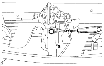
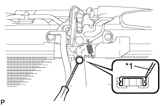
Using a screwdriver, remove the hood lock nut cap.
Text in Illustration *1 Protective Tape Tech Tips
Tape the screwdriver tip before use.
-
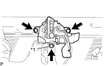
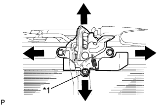
Text in Illustration *1 Hood Lock Bolt Loosen the 2 bolts and hood lock bolt.
-
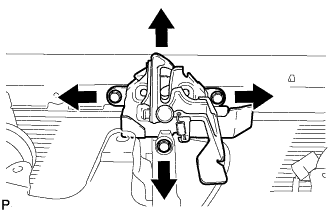
Adjust the hood lock and tighten the 2 bolts and hood lock bolt.
- Torque:
- Bolt
- 7.5 N*m { 76 kgf*cm, 66 in.*lbf }
- Hood Lock Bolt
- 8.0 N*m { 82 kgf*cm, 71 in.*lbf }
-
Check that the striker can engage with the hood lock smoothly.
-
-
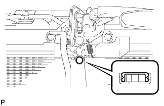
Install a new hood lock nut cap.
-
Install the cool air intake duct seal.
-
-
INSPECT HOOD SUB-ASSEMBLY (for TMC, TMMR Made)
-
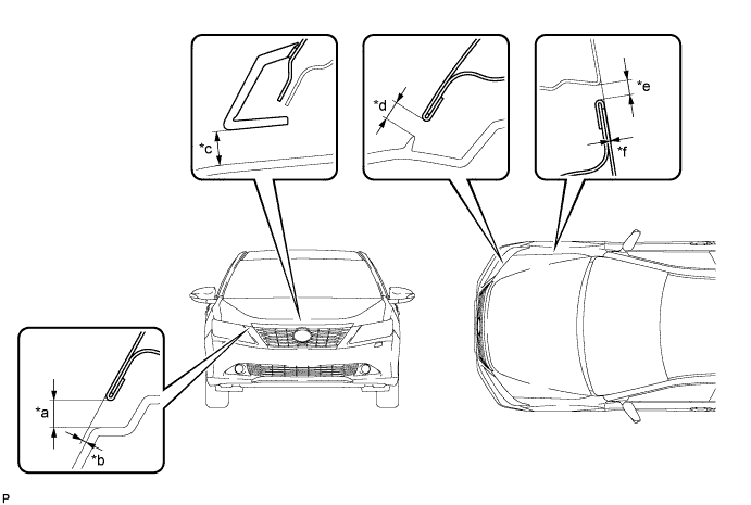
Check that the clearance measurements of areas *a through *f are within each standard range.
Reference Value Area Measurement Area Measurement *a 5.5 to 9.5 mm (0.217 to 0.374 in.) *b -0.8 to 3.2 mm (-0.0315 to 0.126 in.) *c 8.7 to 12.7 mm (0.345 to 0.50 in.) *d 2.8 to 6.8 mm (0.110 to 0.268 in.) *e 2.3 to 5.3 mm (0.0906 to 0.209 in.) *f -1.5 to 1.5 mm (-0.0590 to 0.0590 in.) Tech Tips
Centering bolts are used to mount the hood hinge and hood lock. The hood and hood lock cannot be adjusted with the centering bolts installed. Substitute the centering bolts with standard bolts when making adjustments.
-
-
ADJUST HOOD SUB-ASSEMBLY (for TMC, TMMR Made)
-
Horizontally and vertically adjust the hood.
-
Loosen the 4 hinge bolts of the hood.
-
Adjust the clearance between the hood and front fender by moving the hood.
-
Tighten the 4 hinge bolts after the adjustment.
- Torque:
- 13 N*m { 133 kgf*cm, 10 ft.*lbf }
-
-
Adjust the height of the front end of the hood using the cushion rubbers.
-
Adjust the 2 cushion rubbers so that the heights of the hood and fender are aligned.
Tech Tips
Raise or lower the front end of the hood by turning the 2 cushion rubbers.
-
-
Remove the front bumper assembly.
-
Text in Illustration *1 Protective Tape Adjust the hood lock.
-
Using a screwdriver, remove the hood lock nut cap.
Tech Tips
Tape the screwdriver tip before use.
-
Text in Illustration *1 Hood Lock Bolt Loosen the 2 bolts and hood lock bolt.
-
Adjust the hood lock and tighten the 2 bolts and hood lock bolt.
- Torque:
- 7.5 N*m { 76 kgf*cm, 66 in.*lbf }
-
Check that the striker can engage with the hood lock smoothly.
-
-
Install a new hood lock nut cap.
-
Install the front bumper assembly.
-
-
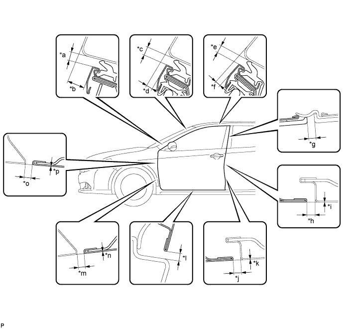
INSPECT FRONT DOOR (for TMMK Made)
-
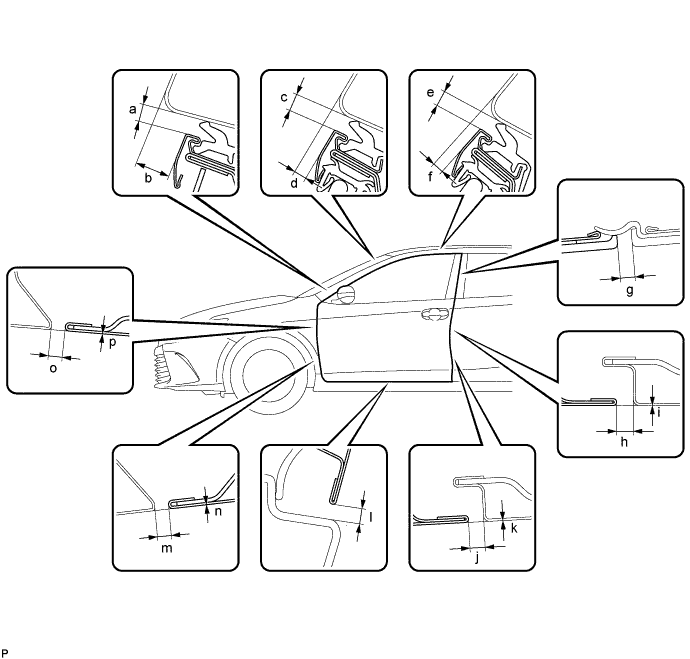
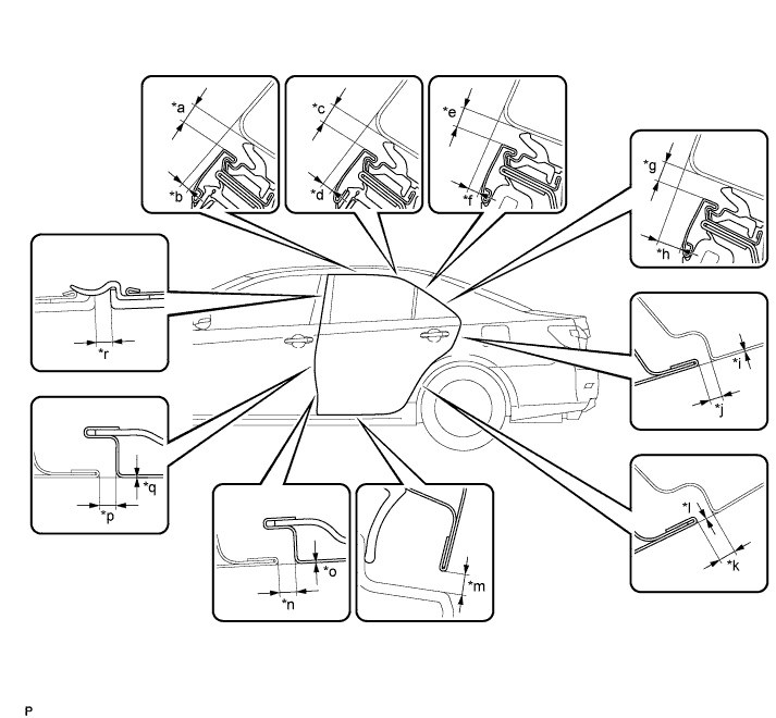
Check that the clearance measurements of areas a through p are within each standard range.
Reference Value Area Measurement Area Measurement a 3.35 to 6.35 mm (0.132 to 0.250 in.) b 8.8 to 11.8 mm (0.346 to 0.465 in.) c 3.35 to 6.35 mm (0.132 to 0.250 in.) d 1.7 to 4.7 mm (0.0669 to 0.185 in.) e 3.35 to 6.35 mm (0.132 to 0.250 in.) f 1.0 to 4.0 mm (0.0394 to 0.157 in.) g 2.3 to 6.3 mm (0.0906 to 0.248 in.) h 2.96 to 4.64 mm (0.117 to 0.183 in.) i -0.84 to 0.84 mm (-0.0331 to 0.0331 in.) j 2.96 to 4.64 mm (0.117 to 0.183 in.) k -0.84 to 0.84 mm (-0.0331 to 0.0331 in.) l 3.05 to 7.25 mm (0.120 to 0.285 in.) m 3.0 to 5.4 mm (0.118 to 0.213 in.) n -1.2 to 1.2 mm (-0.0472 to 0.0472 in.) o 3.0 to 5.4 mm (0.118 to 0.213 in.) p -1.2 to 1.2 mm (-0.0472 to 0.0472 in.) Tech Tips
-
Use the same procedure for the RH side and LH side.
-
The procedure listed below is for the LH side.
-
Centering bolts are used to mount the door hinge to the vehicle body and door. The door cannot be adjusted with the centering bolts installed on it. Substitute the centering bolts with standard bolts when making adjustments.
-
-
REMOVE FRONT WHEEL (for TMMK Made)
-
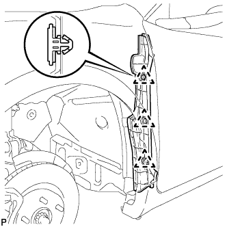
REMOVE FRONT FENDER SEAL (for TMMK Made)
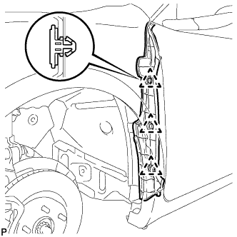
-
Disengage the 3 clips and remove the front fender seal.
-
-
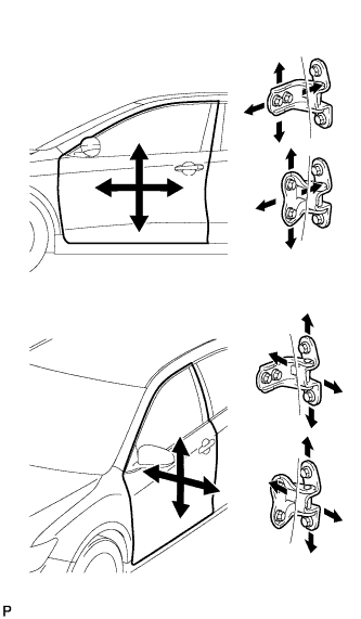
ADJUST FRONT DOOR (for TMMK Made)
Note
Make sure that the turn the engine switch off when adjusting door lock strikers.
-
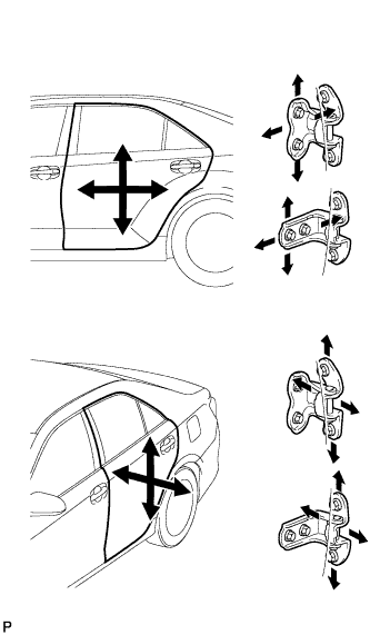
Using SST, loosen the hinge bolts on the vehicle body and adjust the door position.
- SST
- 09812-00010
-
Tighten the hinge bolts on the vehicle body after the adjustment.
- Torque:
- 26 N*m { 265 kgf*cm, 19 ft.*lbf }
-
Loosen the hinge bolts on the door and adjust the door position.
-
Tighten the hinge bolts on the door after the adjustment.
- Torque:
- 26 N*m { 265 kgf*cm, 19 ft.*lbf }
-
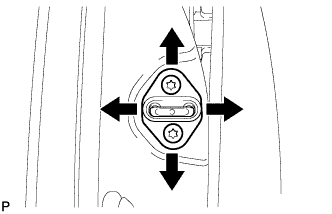
Using a T40 "TORX" socket wrench, slightly loosen the striker mounting screws.
-
Using a brass bar and a hammer, hit the striker to adjust its position.
-
Using a T40 "TORX" socket wrench, tighten the striker mounting screws after adjustment.
- Torque:
- 23 N*m { 235 kgf*cm, 17 ft.*lbf }
-
-
INSTALL FRONT FENDER SEAL (for TMMK Made)
-
Install the front fender seal with 3 new clips.
-
-
INSTALL FRONT WHEEL (for TMMK Made)
-
INSPECT FRONT DOOR (for TMC, TMMR Made)
-
Check that the clearance measurements of areas *a through *p are within each standard range.
Reference Value Area Measurement Area Measurement *a 3.35 to 6.35 mm (0.132 to 0.250 in.) *b 9.0 to 12.0 mm (0.354 to 0.472 in.) *c 3.35 to 6.35 mm (0.132 to 0.250 in.) *d 1.7 to 4.7 mm (0.0669 to 0.185 in.) *e 3.35 to 6.35 mm (0.132 to 0.250 in.) *f 1.0 to 4.0 mm (0.0394 to 0.157 in.) *g 2.3 to 6.3 mm (0.0906 to 0.248 in.) *h 2.96 to 4.64 mm (0.115 to 0.182 in.) *i -0.84 to 0.84 mm (-0.0331 to 0.0331 in.) *j 2.96 to 4.64 mm (0.115 to 0.182 in.) *k -0.84 to 0.84 mm (-0.0331 to 0.0331 in.) *l 2.9 to 7.1 mm (0.114 to 0.280 in.) *m 2.3 to 4.7 mm (0.0906 to 0.185 in.) *n -1.2 to 1.2 mm (-0.0472 to 0.0472 in.) *o 2.3 to 4.7 mm (0.0906 to 0.185 in.) *p -1.2 to 1.2 mm (-0.0472 to 0.0472 in.) Tech Tips
-
Use the same procedure for the RH side and LH side.
-
The procedure listed below is for the LH side.
-
Centering bolts are used to mount the door hinge to the vehicle body and door. The door cannot be adjusted with the centering bolts installed on it. Substitute the centering bolts with standard bolts when making adjustments.
-
-
REMOVE FRONT WHEEL (for TMC, TMMR Made)
-
REMOVE FRONT FENDER SEAL (for TMC, TMMR Made)
-
Disengage the 3 clips and remove the front fender seal.
-
-
ADJUST FRONT DOOR (for TMC, TMMR Made)
Note
Make sure that the turn the ignition switch off when adjusting door lock strikers.
-
Using SST, loosen the hinge bolts on the vehicle body and adjust the door position.
- SST
- 09812-00010
-
Tighten the hinge bolts on the vehicle body after the adjustment.
- Torque:
- 26 N*m { 265 kgf*cm, 19 ft.*lbf }
-
Loosen the hinge bolts on the door and adjust the door position.
-
Tighten the hinge bolts on the door after the adjustment.
- Torque:
- 26 N*m { 265 kgf*cm, 19 ft.*lbf }
-
Using a T40 "TORX" socket wrench, slightly loosen the striker mounting screws.
-
Using a brass bar and a hammer, hit the striker to adjust its position.
-
Using a T40 "TORX" socket wrench, tighten the striker mounting screws after adjustment.
- Torque:
- 23 N*m { 235 kgf*cm, 17 ft.*lbf }
-
-
INSTALL FRONT FENDER SEAL (for TMC, TMMR Made)
-
Install the front fender seal with 3 new clips.
-
-
INSTALL FRONT WHEEL (for TMC, TMMR Made)
-
INSPECT REAR DOOR (for TMMK Made)
-
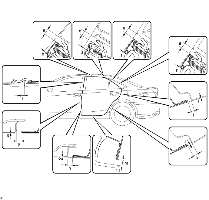
Check that the clearance measurements of areas a through r are within each standard range.
Standard Clearance Area Measurement Area Measurement *a 3.35 to 6.35 mm (0.132 to 0.250 in.) *b 0.5 to 3.5 mm (0.0197 to 0.138 in.) *c 4.1 to 7.1 mm (0.161 to 0.280 in.) *d 0.9 to 3.9 mm (0.0354 to 0.154 in.) *e 4.3 to 7.3 mm (0.169 to 0.287 in.) *f -1.4 to 1.6 mm (-0.0551 to 0.0630 in.) *g 4.3 to 7.3 mm (0.169 to 0.287 in.) *h -1.0 to 2.0 mm (-0.0394 to 0.0787 in.) *i -1.5 to 1.5 mm (-0.0591 to 0.0591 in.) *j 2.7 to 5.7 mm (0.106 to 0.224 in.) *k 2.7 to 5.7 mm (0.106 to 0.224 in.) *l -1.5 to 1.5 mm (-0.0591 to 0.0591 in.) *m 3.05 to 7.25 mm (0.120 to 0.285 in.) *n 2.96 to 4.64 mm (0.117 to 0.183 in.) *o -0.84 to 0.84 mm (-0.0331 to 0.0331 in.) *p 2.96 to 4.64 mm (0.117 to 0.183 in.) *q -0.84 to 0.84 mm (-0.0331 to 0.0331 in.) *r 2.3 to 6.3 mm (0.0906 to 0.248 in.) Tech Tips
-
Use the same procedure for the RH side and LH side.
-
The procedure listed below is for the LH side.
-
Centering bolts are used to mount the door hinge to the vehicle body and door. The door cannot be adjusted with the centering bolts installed. Substitute the centering bolts with standard bolts when making adjustments.
-
-
ADJUST REAR DOOR (for TMMK Made)
Note
Make sure that the turn the ignition switch off when adjusting door lock strikers.
-
Using SST, loosen the hinge bolts on the vehicle body and adjust the door position.
- SST
- 9812-00010
-
Tighten the hinge bolts on the vehicle body after the adjustment.
- Torque:
- 26 N*m { 265 kgf*cm, 19 ft.*lbf }
-
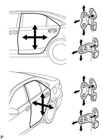
Loosen the hinge bolts on the door and adjust the door position.
-
Tighten the hinge bolts on the door after the adjustment.
- Torque:
- 26 N*m { 265 kgf*cm, 19 ft.*lbf }
-
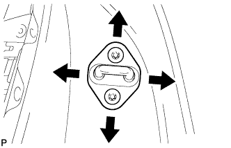
Using a T40 "TORX" socket wrench, slightly loosen the striker mounting screws.
-
Using a brass bar and a hammer, hit the striker to adjust its position.
-
Using a T40 "TORX" socket wrench, tighten the striker mounting screws after adjustment.
- Torque:
- 23 N*m { 235 kgf*cm, 17 ft.*lbf }
-
-
INSPECT REAR DOOR (for TMC, TMMR Made)
-
Check that the clearance measurements of areas *a through *r are within each standard range.
Reference Value Area Measurement Area Measurement *a 3.35 to 6.35 mm (0.132 to 0.250 in.) *b 0.6 to 3.6 mm (0.0236 to 0.142 in.) *c 3.35 to 6.35 mm (0.132 to 0.250 in.) *d 0.9 to 3.9 mm (0.0354 to 0.154 in.) *e 3.35 to 6.35 mm (0.132 to 0.250 in.) *f 1.5 to 4.5 mm (0.0591 to 0.177 in.) *g 3.35 to 6.35 mm (0.132 to 0.250 in.) *h 5.4 to 8.4 mm (0.213 to 0.331 in.) *i -1.5 to 1.5 mm (-0.0591 to 0.0591 in.) *j 2.0 to 5.0 mm (0.0787 to 0.197 in.) *k 2.0 to 5.0 mm (0.0787 to 0.197 in.) *l -1.5 to 1.5 mm (-0.0591 to 0.0591 in.) *m 2.9 to 7.1 mm (0.114 to 0.280 in.) *n 2.96 to 4.64 mm (0.115 to 0.182 in.) *o -0.84 to 0.84 mm (-0.0331 to 0.0331 in.) *p 2.96 to 4.64 mm (0.115 to 0.182 in.) *q -0.84 to 0.84 mm (-0.0331 to 0.0331 in.) *r 2.3 to 6.3 mm (0.0906 to 0.248 in.) Tech Tips
-
Use the same procedure for the RH side and LH side.
-
The procedure listed below is for the LH side.
-
Centering bolts are used to mount the door hinge to the vehicle body and door. The door cannot be adjusted with the centering bolts installed. Substitute the centering bolts with standard bolts when making adjustments.
-
-
ADJUST REAR DOOR (for TMC, TMMR Made)
Note
Make sure that the turn the ignition switch off when adjusting door lock strikers.
-
Using SST, loosen the hinge bolts on the vehicle body and adjust the door position.
- SST
- 9812-00010
-
Tighten the hinge bolts on the vehicle body after the adjustment.
- Torque:
- 26 N*m { 265 kgf*cm, 19 ft.*lbf }
-
Loosen the hinge bolts on the door and adjust the door position.
-
Tighten the hinge bolts on the door after the adjustment.
- Torque:
- 26 N*m { 265 kgf*cm, 19 ft.*lbf }
-
Using a T40 "TORX" socket wrench, slightly loosen the striker mounting screws.
-
Using a brass bar and a hammer, hit the striker to adjust its position.
-
Using a T40 "TORX" socket wrench, tighten the striker mounting screws after adjustment.
- Torque:
- 23 N*m { 235 kgf*cm, 17 ft.*lbf }
-
-
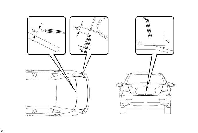
INSPECT LUGGAGE COMPARTMENT DOOR PANEL SUB-ASSEMBLY (for TMMK Made)
-
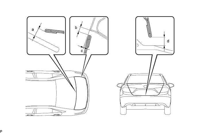
Check that the clearance measurements of areas a through d are within each standard range.
Reference Value Area Measurement Area Measurement *a 6.15 mm (0.242 in.) *b 2.0 to 5.0 mm (0.0787 to 0.197 in.) *c -1.2 to 1.8 mm (-0.0472 to 0.0709 in.) *d 6.05 mm (0.238 in.) -
-
ADJUST LUGGAGE COMPARTMENT DOOR (for TMMK Made)
-
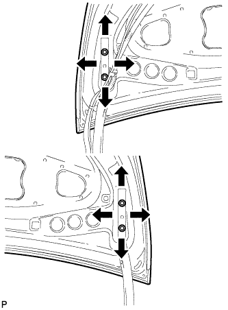
Loosen the door side hinge bolts to adjust the door horizontally and vertically.
- Torque:
- 7.5 N*m { 77 kgf*cm, 66 in.*lbf }
-
Using a T40 "TORX" socket wrench, slightly loosen the striker mounting screws.
-
Using a brass bar and a hammer, hit the striker to adjust its position.
-
Using a T40 "TORX" socket wrench, tighten the striker mounting screws after adjustment.
- Torque:
- 23 N*m { 235 kgf*cm, 17 ft.*lbf }
-
-
INSPECT LUGGAGE COMPARTMENT DOOR PANEL SUB-ASSEMBLY (for TMC, TMMR Made)
-
Check that the clearance measurements of areas *a through *d are within each standard range.
Reference Value Area Measurement Area Measurement *a 6.4 mm (0.252 in.) *b 2.0 to 5.0 mm (0.0787 to 0.197 in.) *c -1.5 to 1.5 mm (-0.0591 to 0.0591 in.) *d 3.7 to 7.7 mm (0.146 to 0.303 in.) Tech Tips
Centering bolts are used to mount the door hinge to the door. The door cannot be adjusted with the centering bolts on. Substitute the centering bolts with standard bolts when making adjustments.
-
-
ADJUST LUGGAGE COMPARTMENT DOOR (for TMC, TMMR Made)
-
Loosen the door side hinge bolts to adjust the door horizontally and vertically.
- Torque:
- 7.5 N*m { 77 kgf*cm, 66 in.*lbf }
-
Using a T40 "TORX" socket wrench, slightly loosen the striker mounting screws.
-
Using a brass bar and a hammer, hit the striker to adjust its position.
-
Using a T40 "TORX" socket wrench, tighten the striker mounting screws after adjustment.
- Torque:
- 23 N*m { 235 kgf*cm, 17 ft.*lbf }
-