WHEN REMOVING,INSTALLING OR REPLACING PARTS WHEEL ALIGNMENT STANDARD
-
MEASURE VEHICLE HEIGHT (for TMMK Made)
Note
-
Before inspecting the wheel alignment, adjust the vehicle height to the specified value.
-
Be sure to perform measurement on a level surface.
-
If it is necessary to go under the vehicle for measurement, confirm that the parking brake is applied and the vehicle is secured with chocks.
-
Inspect while the vehicle is unloaded.
-
The standard value shown here is a value that is used for adjusting the wheel alignment and does not indicate the height of an actual vehicle.
-
Bounce the vehicle up and down at the corners to stabilize the suspension.
-
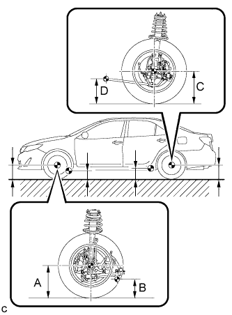
Measure the vehicle height.
-
A: Ground clearance of front wheel center
-
B: Ground clearance of No. 2 lower suspension arm bushing set bolt center
-
C: Ground clearance of rear wheel center
-
D: Ground clearance of strut rod set bolt center
Measurement points:
Vehicle Height (Unloaded Vehicle) Front A - B Rear C - D 125 mm (4.92 in.) 55 mm (2.17 in.) -
-
-
MEASURE VEHICLE HEIGHT (for TMC, TMMR Made)
Note
-
Before inspecting the wheel alignment, adjust the vehicle height to the specified value.
-
Be sure to perform measurement on a level surface.
-
If it is necessary to go under the vehicle for measurement, confirm that the parking brake is applied and the vehicle is secured with chocks.
-
Inspect while the vehicle is unloaded.
-
The standard value shown here is a value that is used for adjusting the wheel alignment and does not indicate the height of an actual vehicle.
-
Bounce the vehicle up and down at the corners to stabilize the suspension.
-
Measure the vehicle height.
-
A: Ground clearance of front wheel center
-
B: Ground clearance of No. 2 lower suspension arm bushing set bolt center
-
C: Ground clearance of rear wheel center
-
D: Ground clearance of strut rod set bolt center
Measurement points:
Vehicle Height (Unloaded Vehicle) Tire Size Front A - B Rear C - D 215/60R16 112 mm (4.41 in.)
112 mm (4.41 in.)*1
114 mm (4.49 in.)*3
40 mm (1.57 in.)
41 mm (1.61 in.)*1
40 mm (1.57 in.)*3
215/55R17 116 mm (4.57 in.)
113 mm (4.45 in.)*1
117 mm (4.61 in.)*2
46 mm (1.81 in.)
42 mm (1.65 in.)*1
47 mm (1.85 in.)*2
-
*1: for Russia 2AR-FE
-
*2: for Russia 2GR-FE
-
*3: for Russia 6AR-FSE
-
-
-
INSPECT CAMBER, CASTER AND STEERING AXIS INCLINATION (for TMMK Made)
Note
Inspect while the vehicle is unloaded.
-
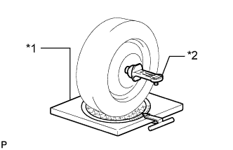
Text in Illustration *1 Turning Radius Gauge *2 Camber-caster-kingpin Gauge Install a camber-caster-kingpin gauge and place the front wheels on the center of a turning radius gauge.
-
Inspect the camber, caster and steering axis inclination.
Camber (Unloaded Vehicle) Camber Inclination Right-left Difference -0°42' +/- 45' (-0.70° +/- 0.75°) 45' (0.75°) or less Caster (Unloaded Vehicle) Caster Inclination Right-left Difference 2°58' +/- 45' (2.97° +/- 0.75°) 45' (0.75°) or less Steering Axis (Unloaded Vehicle) Steering Axis Inclination Reference 12°16' (12.27°)
-
* For Russia
-
-
-
INSPECT CAMBER, CASTER AND STEERING AXIS INCLINATION (for TMC, TMMR Made)
Note
Inspect while the vehicle is unloaded.
-
Text in Illustration *1 Turning Radius Gauge *2 Camber-caster-kingpin Gauge Install a camber-caster-kingpin gauge and place the front wheels on the center of a turning radius gauge.
-
Inspect the camber, caster and steering axis inclination.
Camber (Unloaded Vehicle) Tire Size Camber Inclination Right-left Difference 215/60R16 -0°35' +/- 45' (-0.58° +/- 0.75°) 45' (0.75°) or less 215/55R17 -0°35' +/- 45' (-0.58° +/- 0.75°) Caster (Unloaded Vehicle) Tire Size Caster Inclination Right-left Difference 215/60R16 2°45' +/- 45' (2.75° +/- 0.75°)
2°50' +/- 45' (2.83° +/- 0.75°)*1
2°45' +/- 45' (2.75° +/- 0.75°)*2
45' (0.75°) or less 215/55R17 2°50' +/- 45' (2.83° +/- 0.75°)
-
*1: for Russia 2AR-FE
-
*2: for Russia 6AR-FSE
Steering Axis (Unloaded Vehicle) Tire Size Steering Axis Inclination Reference 215/60R16 11°55' (11.92°)
12°00' (12.00°)*1
215/55R17 12°05' (12.08°)
12°00' (12.00°)*2
12°05' (12.08°)*3
-
*1: for Russia
-
*2: for Russia 2AR-FE
-
*3: for Russia 2GR-FE
-
-
-
INSPECT TOE-IN (FRONT) (for TMMK Made)
Note
Inspect while the vehicle is unloaded.
-
Bounce the vehicle up and down at the corners to stabilize the suspension.
-
Release the parking brake and move the shift lever to N.
-
Push the vehicle straight ahead approximately 5 m (16.4 ft.). (Step C)
-
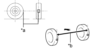
Text in Illustration *a Tread Center Mark *b Dimension B 
Front of the Vehicle Put tread center marks on the rearmost points of the front wheels and measure the distance between the marks (dimension B).
-
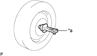
Slowly push the vehicle straight ahead to cause the front wheels to rotate 180°. Use the front tire valve as a reference point.
Tech Tips
Do not allow the wheels to rotate more than 180°. If the wheels rotate more than 180°, perform the procedure from Step C again.
-
Text in Illustration *a Dimension A Front of the Vehicle Measure the distance between the tread center marks on the front of the wheels (dimension A).
Toe-in (Unloaded Vehicle) Specified Condition C + D: 0°00' +/- 0°10' (0.00° +/- 0.17°) B - A: 0 +/- 2.0 mm (0 +/- 0.0787 in.) Tech Tips
Measure "B - A" only when "C + D" cannot be measured.
If the toe-in is not within the specified range, adjust it at the rack ends.
-
-
INSPECT TOE-IN (FRONT) (for TMC, TMMR Made)
Note
Inspect while the vehicle is unloaded.
-
Bounce the vehicle up and down at the corners to stabilize the suspension.
-
Release the parking brake and move the shift lever to N.
-
Push the vehicle straight ahead approximately 5 m (16.4 ft.). (Step C)
-
Text in Illustration *a Tread Center Mark *b Dimension B Front of the Vehicle Put tread center marks on the rearmost points of the front wheels and measure the distance between the marks (dimension B).
-
Slowly push the vehicle straight ahead to cause the front wheels to rotate 180°. Use the front tire valve as a reference point.
Tech Tips
Do not allow the wheels to rotate more than 180°. If the wheels rotate more than 180°, perform the procedure from Step C again.
-
Text in Illustration *a Dimension A Front of the Vehicle Measure the distance between the tread center marks on the front of the wheels (dimension A).
Toe-in (Unloaded Vehicle) Specified Condition C + D: 0°00' +/- 0°11' (0.00° +/- 0.18°) B - A: 0 +/- 2.0 mm (0 +/- 0.0787 in.) Tech Tips
Measure "B - A" only when "C + D" cannot be measured.
If the toe-in is not within the specified range, adjust it at the rack ends.
-
-
INSPECT WHEEL ANGLE (for TMMK Made)
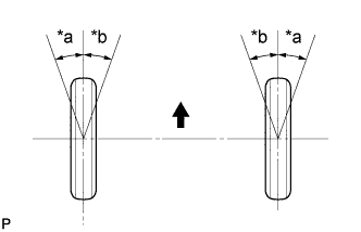
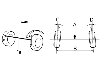
Text in Illustration *a Inside *b Outside Front of the Vehicle
-
Put tread center marks on the rearmost points of a turning radius gauge.
-
Turn the steering wheel fully to the left and right and measure the turning angle.
Note
Inspect while the vehicle is unloaded.
Wheel Turning Angle (Unloaded Vehicle) Inside Wheel Outside Wheel 37°13' +/- 2° (37.22° +/- 2°) 32°49' +/- 2° (32.81° +/- 2°)
-
If the right and left inside wheel angles differ from the specified value, check and adjust the right and left rack end lengths.
-
-
-
INSPECT WHEEL ANGLE (for TMC, TMMR Made)
Text in Illustration *a Inside *b Outside Front of the Vehicle
-
Put tread center marks on the rearmost points of a turning radius gauge.
-
Turn the steering wheel fully to the left and right and measure the turning angle.
Note
Inspect while the vehicle is unloaded.
Wheel Turning Angle (Unloaded Vehicle) Tire Size Inside Wheel Outside Wheel 215/60R16 39°58' +/- 2° (39.97° +/- 2°)
38°57' +/- 2° (38.95° +/- 2°)*1
38°52' +/- 2° (38.87° +/- 2°)*3
33°59' (33.98°)
33°59' (33.98°)*1
33°56' (33.93°)*3
215/55R17 38°50' +/- 2° (38.83° +/- 2°)
38°55' +/- 2° (38.92° +/- 2°)*1
38°49' +/- 2° (38.82° +/- 2°)*2
33°54' (33.90°)
33°58' (33.97°)*1
33°53' (33.88°)*2
-
*1: for Russia 2AR-FE
-
*2: for Russia 2GR-FE
-
*3: for Russia 6AR-FSE
-
If the right and left inside wheel angles differ from the specified value, check and adjust the right and left rack end lengths.
-
-
-
INSPECT CAMBER (REAR) (for TMMK Made)
Note
Inspect while the vehicle is unloaded.
-
Text in Illustration *a Camber-caster-kingpin Gauge Install a camber-caster-kingpin gauge.
-
Inspect the camber.
Camber (Unloaded Vehicle) Camber Inclination Right-left Difference -1°15' +/- 45' (-1.25° +/- 0.75°) 45' (0.75°) or less Tech Tips
Camber is not adjustable. If the measurement is not within the specified range, inspect the suspension parts for damage and/or wear, and replace them if necessary.
-
-
INSPECT CAMBER (REAR) (for TMC, TMMR Made)
Note
Inspect while the vehicle is unloaded.
-
Text in Illustration *a Camber-caster-kingpin Gauge Install a camber-caster-kingpin gauge.
-
Inspect the camber.
Camber (Unloaded Vehicle) Tire Size Camber Inclination Right-left Difference 215/60R16 -1°08' +/- 45' (-1.13° +/- 0.75°)
-1°09' +/- 45' (-1.15° +/- 0.75°)*1
-1°07' +/- 45' (-1.12° +/- 0.75°)*3
45' (0.75°) or less 215/55R17 -1°11' +/- 45' (-1.18° +/- 0.75°)
-1°09' +/- 45' (-1.15° +/- 0.75°)*1
-1°12' +/- 45' (-1.20° +/- 0.75°)*2
-
*1: for Russia 2AR-FE
-
*2: for Russia 2GR-FE
-
*3: for Russia 6AR-FSE
Tech Tips
Camber is not adjustable. If the measurement is not within the specified range, inspect the suspension parts for damage and/or wear, and replace them if necessary.
-
-
-
INSPECT TOE-IN (REAR) (for TMMK Made)
Note
Inspect while the vehicle is unloaded.
-
Bounce the vehicle up and down at the corners to stabilize the suspension.
-
Release the parking brake and move the shift lever to N.
-
Push the vehicle straight ahead approximately 5 m (16.4 ft.). (Step A)
-

Text in Illustration *a Tread Center Mark *b Dimension B Front of the Vehicle Put tread center marks on the rearmost points of the rear wheels and measure the distance between the marks (dimension B).
-
Slowly push the vehicle straight ahead to cause the rear wheels to rotate 180°. Use the rear tire valve as a reference point.
Tech Tips
Do not allow the wheels to rotate more than 180°. If the wheels rotate more than 180°, perform the procedure from Step A again.
-

Text in Illustration *a Dimension A Front of the Vehicle Measure the distance between the tread center marks on the front of the rear wheels (dimension A).
Toe-in (Unloaded Vehicle) Specified Condition C + D: 0°13' +/- 0°10' (0.21° +/- 0.17°) B - A: 2.5 +/- 2.0 mm (0.0984 +/- 0.0787 in.) Tech Tips
Measure "B - A" only when "C + D" cannot be measured.
If the toe-in is not within the specified range, adjust it at the rear No. 2 suspension arms.
-
-
INSPECT TOE-IN (REAR) (for TMC, TMMR Made)
Note
Inspect while the vehicle is unloaded.
-
Bounce the vehicle up and down at the corners to stabilize the suspension.
-
Release the parking brake and move the shift lever to N.
-
Push the vehicle straight ahead approximately 5 m (16.4 ft.). (Step A)
-
Text in Illustration *a Tread Center Mark *b Dimension B Front of the Vehicle Put tread center marks on the rearmost points of the rear wheels and measure the distance between the marks (dimension B).
-
Slowly push the vehicle straight ahead to cause the rear wheels to rotate 180°. Use the rear tire valve as a reference point.
Tech Tips
Do not allow the wheels to rotate more than 180°. If the wheels rotate more than 180°, perform the procedure from Step A again.
-
Text in Illustration *a Dimension A Front of the Vehicle Measure the distance between the tread center marks on the front of the rear wheels (dimension A).
Toe-in (Unloaded Vehicle) Specified Condition C + D: 0°22' +/- 0°11' (0.37° +/- 0.18°) B - A: 4.0 +/- 2.0 mm (0.157 +/- 0.0787 in.) Tech Tips
Measure "B - A" only when "C + D" cannot be measured.
If the toe-in is not within the specified range, adjust it at the rear No. 2 suspension arms.
-