FIT STANDARD / ADJUSTMENT METHOD ADJUSTMENT
-
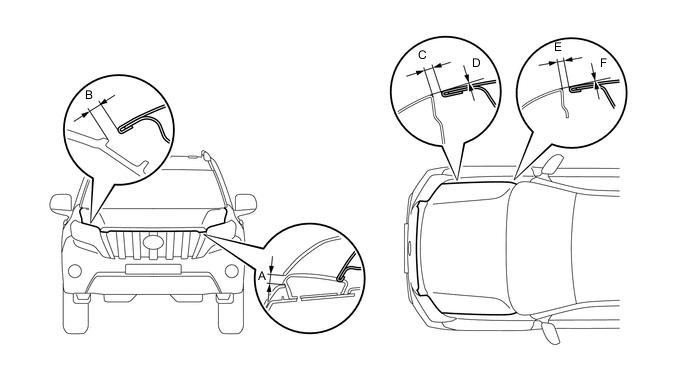
INSPECT HOOD SUB-ASSEMBLY
-
Check that the clearance measurements of areas A through F are within each standard range.
Tech Tips
-
Use the same procedure for RHD and LHD vehicles.
-
The procedure listed below is for LHD vehicles.
-
Centering bolts are used to mount the hood hinge and hood lock. The hood and hood lock cannot be adjusted with the centering bolts installed. Substitute the centering bolts with standard bolts when making adjustments.
-
Centering bolts are used to mount the hood hinge and hood lock. The hood and hood lock cannot be adjusted with the centering bolts installed. Substitute the centering bolts with standard bolts when making adjustments.
-
-
-
ADJUST HOOD SUB-ASSEMBLY
-
Adjust the hood position.
-

Loosen the 4 hinge bolts on the hood.
-
Move the hood and adjust the clearance between the hood and front fender.
-
Tighten the 4 hinge bolts on the hood.
- Torque:
- 13 N*m { 133 kgf*cm, 10 ft.*lbf }
-
-
Adjust the height of the front end of the hood using the cushion rubbers.
-
Adjust the 2 cushion rubbers so that the heights of the hood and fender are aligned.
Tech Tips
Raise or lower the front end of the hood by turning the 2 cushion rubbers.
-
-
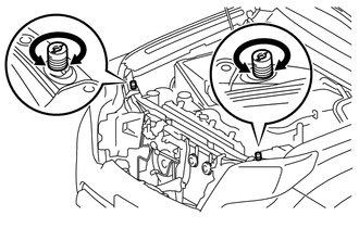
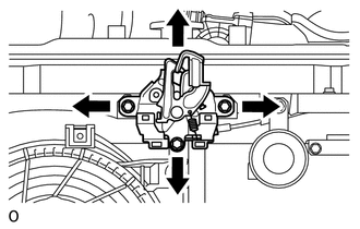
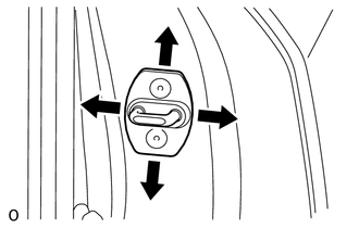
Adjust the hood lock.
-
Loosen the 3 bolts.
-
Adjust the hood lock and tighten the 3 bolts.
- Torque:
- 7.5 N*m { 76 kgf*cm, 66 in.*lbf }
-
Check that the striker can smoothly engage with the hood lock.
-
-
-
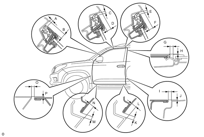
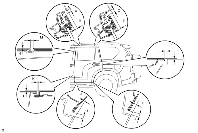
INSPECT FRONT DOOR
-
for 5 Door:
-
Check that the clearance measurements of areas A through P are within the standard range.

-
-
for 3 Door:
-
Check that the clearance measurements of areas A through P are within the standard range.
-
Tech Tips
-
Use the same procedure for the RH and LH sides.
-
The procedure listed below is for the LH side.
-
Centering bolts are used to mount the door hinge to the vehicle body and door. The door cannot be adjusted with the centering bolts installed on it. Substitute the centering bolts with standard bolts when making adjustments.
-
-
ADJUST FRONT DOOR
-
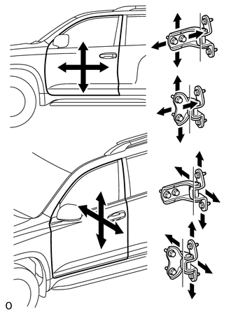
Using SST, loosen the hinge bolts on the vehicle body and adjust the door position.
- SST
- 09812-00010
-
Tighten the hinge bolts on the vehicle body.
- Torque:
- 26 N*m { 265 kgf*cm, 19 ft.*lbf }
-
Loosen the hinge bolts on the door and adjust the door position.
-
Tighten the hinge bolts on the door.
- Torque:
- 26 N*m { 265 kgf*cm, 19 ft.*lbf }
-
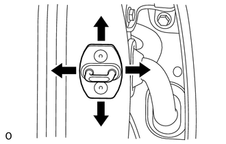
Using a T40 "TORX" socket wrench, slightly loosen the striker mounting screws.
-
Using a brass bar and hammer, hit the striker to adjust its position.
-
Using a T40 "TORX" socket wrench, tighten the striker mounting screws.
- Torque:
- 23 N*m { 235 kgf*cm, 17 ft.*lbf }
-
-
INSPECT REAR DOOR
-
Check that the clearance measurements of areas A through N are within the standard range.
Tech Tips
-
Use the same procedure for the RH and LH sides.
-
The procedure listed below is for the LH side.
-
Centering bolts are used to mount the door hinge to the vehicle body and door. The door cannot be adjusted with the centering bolts installed. Substitute the centering bolts with standard bolts when making adjustments.
-
-
-
ADJUST REAR DOOR
-
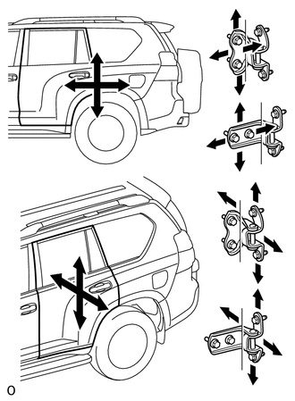
Using SST, loosen the hinge bolts on the vehicle body and adjust the door position.
- SST
- 09812-00010
-
Tighten the hinge bolts on the vehicle body.
- Torque:
- 26 N*m { 265 kgf*cm, 19 ft.*lbf }
-
Loosen the hinge bolts on the door and adjust the door position.
-
Tighten the hinge bolts on the door.
- Torque:
- 26 N*m { 265 kgf*cm, 19 ft.*lbf }
-
Using a T40 "TORX" socket wrench, slightly loosen the striker mounting screws.
-
Using a brass bar and hammer, hit the striker to adjust its position.
-
Using a T40 "TORX" socket wrench, tighten the striker mounting screws.
- Torque:
- 23 N*m { 235 kgf*cm, 17 ft.*lbf }
-
-
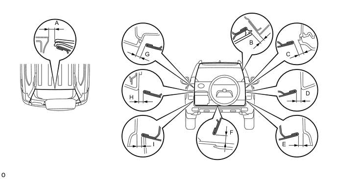
INSPECT BACK DOOR
-
w/ Back Door Tire Carrier:
-
Check that the clearance measurements of areas A through I are within the standard range.
-
-
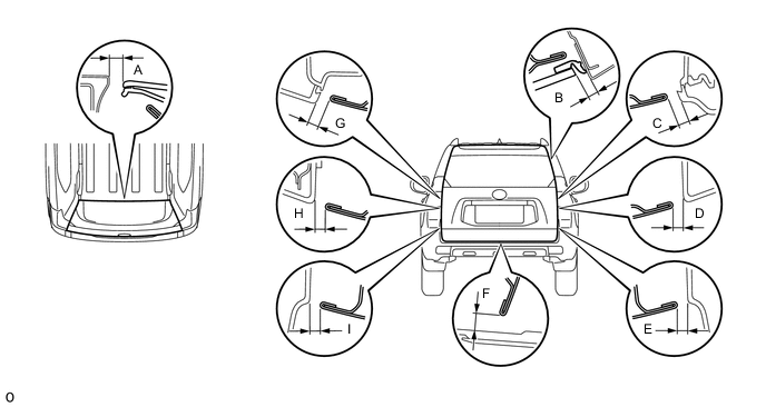
w/o Back Door Tire Carrier:
-
Check that the clearance measurements of areas A through I are within the standard range.
-
Tech Tips
Centering bolts are used to mount the door hinge to the vehicle body and door. The door cannot be adjusted with the centering bolts installed. Substitute the centering bolts with standard bolts (with washers) when making adjustments.
-
-
ADJUST BACK DOOR
-
w/ Back Door Tire Carrier:
-
Remove the spare wheel cover pad.
-
Remove the spare wheel cover.
-
Remove the spare tire.
-
-
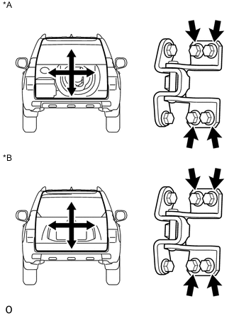
Text in Illustration *A w/ Back Door Tire Carrier *B w/o Back Door Tire Carrier Loosen the hinge bolts on the body and adjust the position of the door.
-
Tighten the hinge bolts on the body.
- Torque:
- 26 N*m { 265 kgf*cm, 19 ft.*lbf }
-
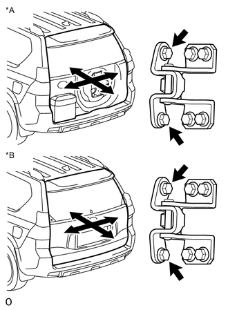
Text in Illustration *A w/ Back Door Tire Carrier *B w/o Back Door Tire Carrier Loosen the hinge bolts on the door and adjust the position of the door.
-
Tighten the hinge bolts on the door.
- Torque:
- 36 N*m { 367 kgf*cm, 27 ft.*lbf }
-
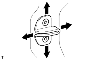
Using a T40 "TORX" socket, adjust the striker position by slightly loosening the striker mounting screws and then hitting the striker with a plastic-faced hammer.
-
Using a T40 "TORX" socket, tighten the striker mounting screws.
- Torque:
- 23 N*m { 235 kgf*cm, 17 ft.*lbf }
-
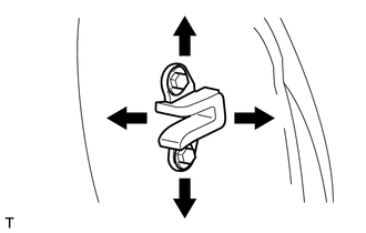
Using a T30 "TORX" socket, adjust the back door side male stopper position by slightly loosening the stopper mounting screws and then hitting the stopper with a plastic-faced hammer.
-
Using a T30 "TORX" socket, tighten the male stopper mounting screws.
- Torque:
- 7.0 N*m { 71 kgf*cm, 62 in.*lbf }
-
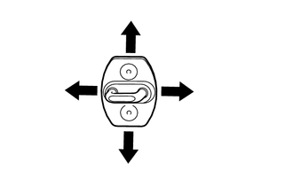
Loosen the back door side female stopper bolts and adjust the stopper position.
-
Tighten the female stopper bolts.
- Torque:
- 7.0 N*m { 71 kgf*cm, 62 in.*lbf }
-
w/ Back Door Tire Carrier:
-
Install the spare tire.
-
Install the spare wheel cover.
-
Install the spare wheel cover pad.
-
-