FRAME(for 3 Door) TWO-DIMENSIONAL DISTANCE
-
Upper Face
Tech Tips
For symbols, capital letters indicate right side of vehicle, small letters indicate left side of vehicle (seen from rear).
Measuring Point Name Symbol Name Hole Diameter
mm (in.)
A, a Front bumper reinforcement installation nut M10 (0.39) B, b No. 1 body mounting hole φ26 (1.02) C, c Front spring support installation hole φ12.15 (0.4783) D, d No. 2 body mounting hole φ43 (1.69) E, e Side rail inner channel standard hole 16X16
(0.63X0.63)
F, f No. 3 body mounting hole φ43 (1.69) G, g No. 4 body mounting hole φ43 (1.69) 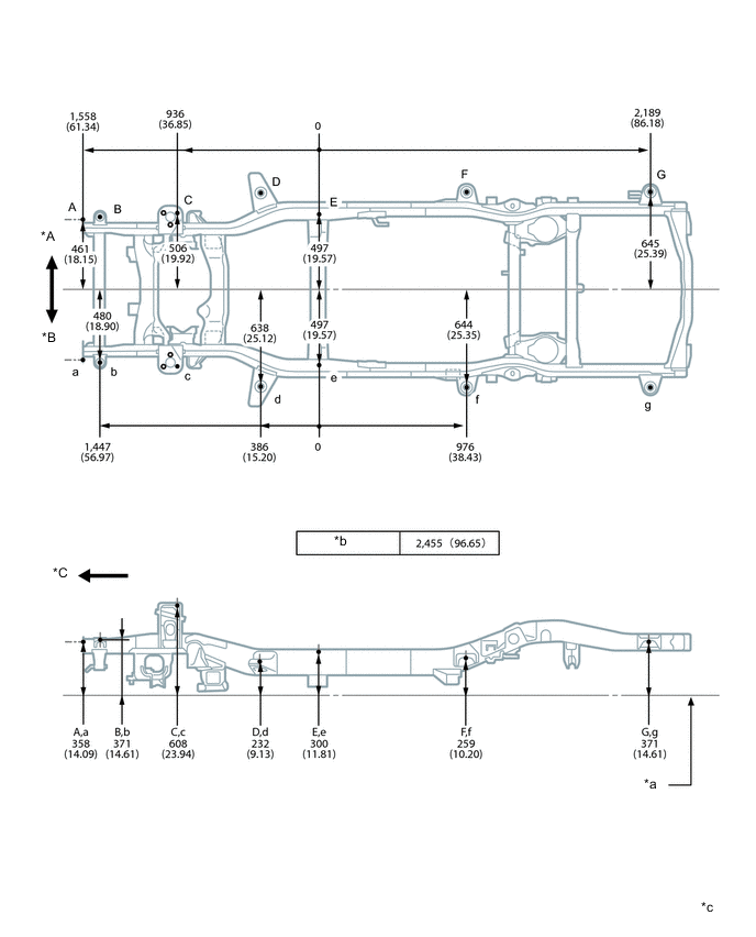
*A RH *B LH *C Front - - *a Imaginary Datum Line *b Wheel base *c mm
(in.)
- - -
Lower Face
Tech Tips
For symbols, capital letters indicate right side of vehicle, small letters indicate left side of vehicle (seen from rear).
Measuring Point Name Symbol Name Hole Diameter
mm (in.)
A, a Front bumper reinforcement installation nut M10 (0.39) B, b Front stabilizer bracket installation nut M10 (0.39) C, c Lower arm installation hole 40X22
(1.57X0.87)
D, d Lower arm installation hole 34.5X16.5
(1.358X0.650)
E, e Side rail inner channel standard hole 16X16
(0.63X0.63)
F, f Lower arm installation hole φ14.2 (0.559) G, g Upper arm installation hole φ12.2 (0.480) H, h Rear shock absorber installation hole φ25 (0.98) I Lateral control rod installation hole φ15 (0.59) J, j Transport hook installation nut M12 (0.47) 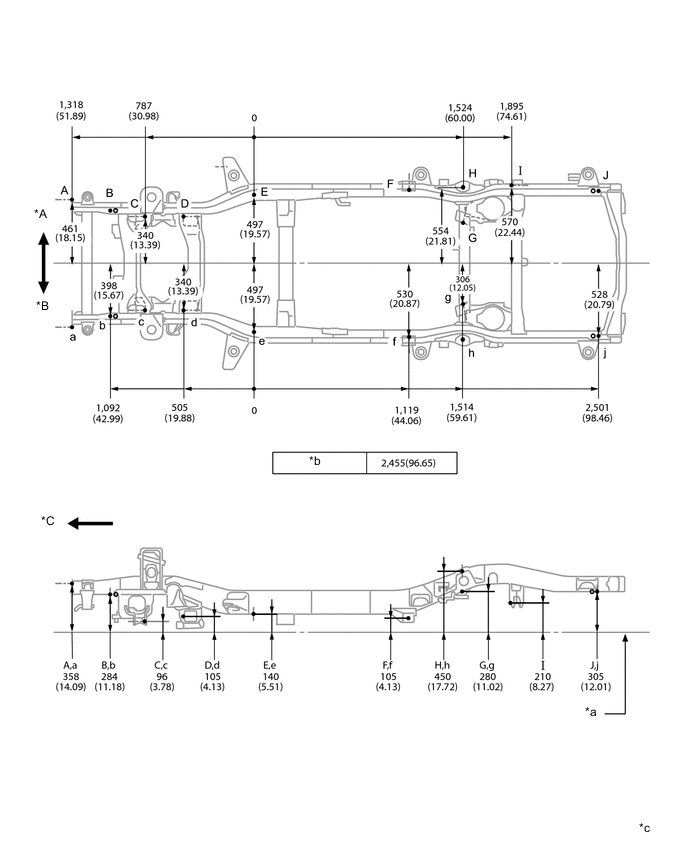
*A RH *B LH *C Front - - *a Imaginary Datum Line *b Wheel base *c mm
(in.)
- -