WHEN REMOVING,INSTALLING OR REPLACING PARTS WHEEL ALIGNMENT STANDARD
Note
If the wheel alignment has been adjusted, and if suspension or underbody components have been removed/installed or replaced, be sure to perform the following initialization procedure in order for the system to function normally:
-
Perform zero point calibration of the yaw rate and acceleration sensor and the test mode inspection.
-
MEASURE VEHICLE HEIGHT
Note
Before inspecting the wheel alignment, adjust the vehicle height to the specification.
-
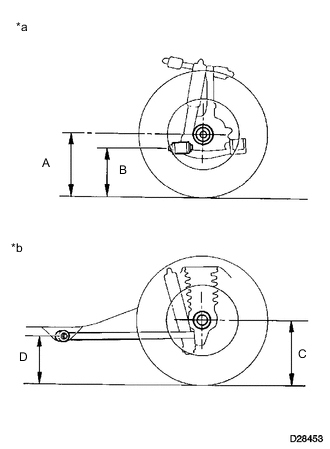
Text in Illustration *a Front Side *b Rear Side Press down on the vehicle several times to stabilize the suspension, and then measure the vehicle height.
-
(*1) Light duty
-
(*2) Heavy duty
If the vehicle height is not as specified, adjust the height by pressing down on the vehicle several times to stabilize the suspension.
Note
The standard value shown here is a value that is used for adjusting the wheel alignment and does not indicate the height of an actual vehicle.
-
-
-
INSPECT CAMBER, CASTER AND STEERING AXIS INCLINATION
-
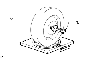
Text in Illustration *a Wheel Alignment Tester *b Gauge Install a camber-caster-kingpin gauge or place the front wheels on the center of a wheel alignment tester.
-
Inspect the camber, caster and steering axis inclination.
-
(*1) Light duty
-
(*2) Heavy duty
-
(*1) Light duty
-
(*2) Heavy duty
-
(*1) Light duty
-
(*2) Heavy duty
-
-
-
INSPECT TOE-IN
-
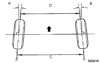
Bounce the vehicle up and down at the corners to stabilize the suspension and inspect the toe-in.
Text in Illustration 
Front
-
(*1) Light duty
-
(*2) Heavy duty
-
-
-
INSPECT WHEEL ANGLE
-
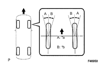
Text in Illustration *a Inside *b Outside Front Turn the steering wheel to the left and right full lock positions, and measure the turning angle.
-
(*1) Light duty
-
(*2) Heavy duty
-
-