UNDER BODY TWO-DIMENSIONAL DISTANCE
Tech Tips
-
For symbols, capital letters indicate right side of vehicle, small letters indicate left side of vehicle (seen from rear).
-
Point B, b and C, c on the vehicle are asymmetrical.
| Symbol | Name | Hole Diameter mm (in.) |
|---|---|---|
| A, a | Radiator lower support standard hole | φ10 (0.39) |
| B, b | Front crossmember installation nut | M12 (0.47) |
| C, c | Front side member standard hole | φ18 (0.71) |
| D, d | Front suspension crossmember installation nut | M14 (0.55) |
| E, e | Front spring support installation hole | φ12.5 (0.492) |
| F, f | Front suspension crossmember installation nut | M14 (0.55) |
| G, g | Front torque box standard hole | φ25 (0.98) |
| H, h | Front side member standard hole | φ22 (0.87) |
| I, i | Front side inner rear member standard hole | φ18 (0.71) |
| J, j | Front floor pan standard hole | φ18 (0.71) |
| K, k | Rear torque box reinforcement standard hole | φ18 (0.71) |
| L, l | Trailing arm bracket installation hole | φ16 (0.63) |
| M, m | Rear spring plate standard hole | φ10 (0.39) |
| N, n | Rear shock absorber installation hole | φ25 (0.98) |
| O, o | Rear floor side member standard hole | φ16 (0.63) |
| P, p | Rear floor side member standard hole | φ18 (0.71) |
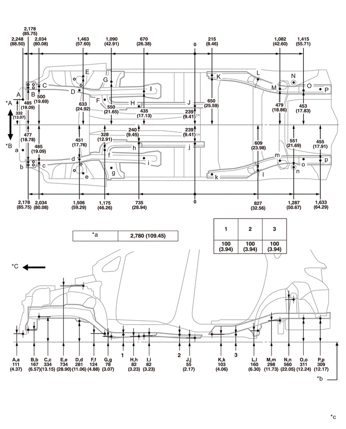
| *A | RH | *B | LH |
| *C | Front | - | - |
| *a | Wheel base | *b | Imaginary Datums Line |
| *c | mm (in.) |
- | - |