FRONT BODY PILLAR CUT AND JOIN REPLACEMENT SECTIONS
-
-
With the cowl top side panel removed.
-
REMOVAL
Symbol Meaning 
Remove Weld Points 
Remove Weld Points 
Remove Weld Points 
Cut with Disc Sander etc. 
Cut and Join Location 
Cut Location for Supply Parts
-
Reuse *a, as the area of the outer panel that is cut and joined is to the rear of the supplied part cut position.
-
Carefully cut the rocker outer reinforce so not to damage *b.
-
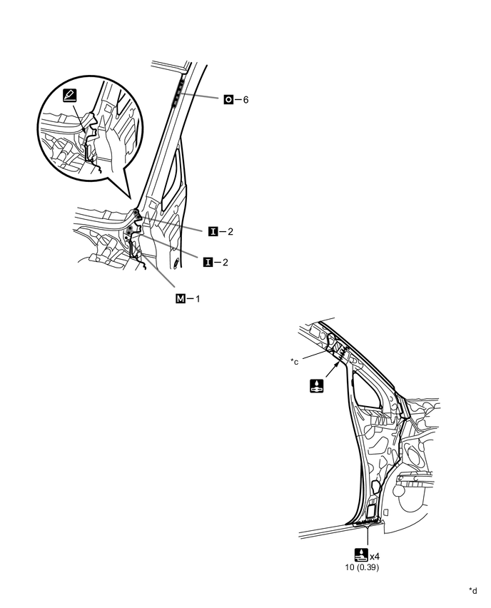
*c indicates the location of the foamed sealing material. Be careful when cutting as the foamed sealing material is located near the cutting position.
REMOVAL POINT
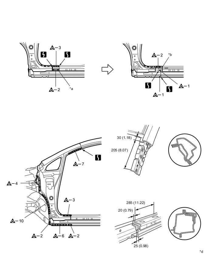
*d mm (in.) - - 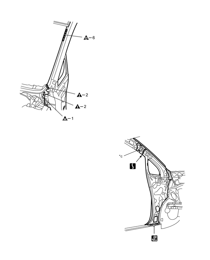
-
-
INSTALLATION
Symbol Meaning Remove Weld Points 
Spot Weld 
Plug Weld 
Plug Weld 
Plug Weld Cut and Join Location 
Fillet Weld 
Butt Weld 
Body Sealer
-
If the entire supply part is not needed, remove the part of the supply part that is needed.
-
Carefully cut the rocker outer reinforce so not to damage *a.
-
Before installing a new part, apply body sealer.
Tech Tips
Apply body sealer in an even, continuous bead.
-
Before temporarily installing the new parts, weld the rocker outer reinforce, front body pillar lower reinforce, front body inner pillar and front body outer pillar with the standard number of welding points.
-
Inspect the fitting of the related parts around the new parts before welding. This affects the appearance of the finish.
-
Temporarily install the new parts and measure each part of the new parts in accordance with the body dimension diagram. (See the body dimensions)
-
After welding the front body pillar to the vehicle side, install the *b.
-
*c indicates the location of the foamed sealing material. Be careful when welding as the foamed sealing material is located near the area that is cut and joined together.
-
After welding, apply the foamed sealing material to the corresponding parts. (See the painting / coating)
-
After welding, apply body sealer to the corresponding parts. (See the painting / coating)
-
After applying the top coat, apply anti-rust agent to the internal panel portion of the closed section structural weld points.
INSTALLATION POINT
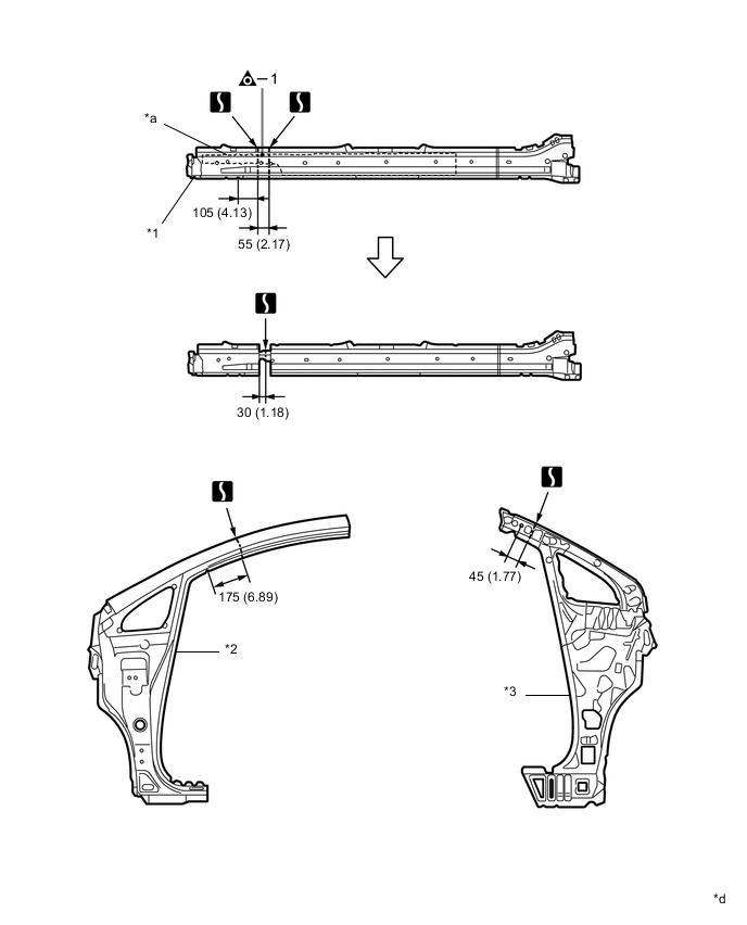
*1 Rocker Outer Reinforce *2 Front Body Outer Pillar *3 Front Body Inner Pillar - - *d mm (in.) - - 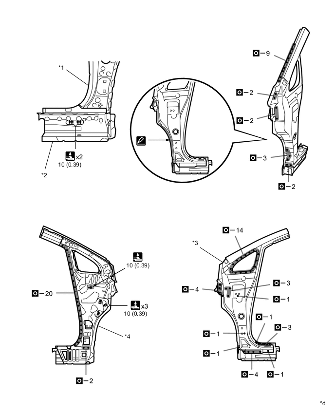
*1 Front Body Pillar Lower Reinforce *2 Rocker Outer Reinforce *3 Front Body Outer Pillar *4 Front Body Inner Pillar *d mm (in.) - - 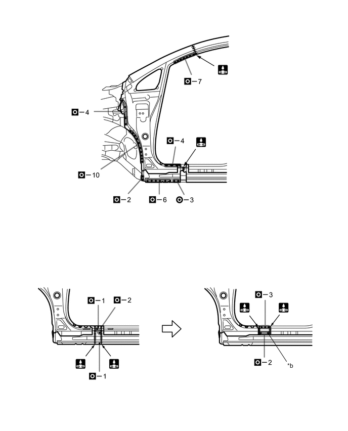
*d mm (in.) - - -