WHEN REMOVING,INSTALLING,REPAIRING OR REPLACING PARTS WHEEL ALIGNMENT STANDARD
Note
If the wheel alignment has been adjusted, or if suspension or underbody components have been removed/installed or replaced, be sure to perform the following initialization procedure in order for the system to function normally.
-
Disconnect the cable from the negative battery terminal for more than 2 seconds.
-
Reconnect the cable to the negative battery terminal.
-
Perform zero point calibration of the yaw rate and acceleration sensor and test mode inspection.
-
MEASURE VEHICLE HEIGHT
-
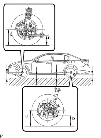
Bounce the vehicle at the corners up and down to stabilize the suspension and inspect vehicle height.
Note
-
The standard value shown here is a value that is used for adjusting the wheel alignment and does not indicate the height of an actual vehicle.
-
Before inspecting the wheel alignment, adjust the vehicle height to the specified value.
Tech Tips
Bounce the vehicle at the corners up and down to stabilize the suspension and inspect the vehicle height.
-
-
-
INSPECT CAMBER, CASTER AND STEERING AXIS INCLINATION (FRONT WHEEL ALIGNMENT)
-
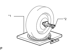
Text in Illustration *1 Wheel Alignment Tester *2 Gauge Put the front wheel on the center of the alignment tester.
-
Remove the center ornament.
-
Install the camber-caster-steering axis inclination gauge at the center of the axle hub or drive shaft.
-
Inspect the camber, caster and steering axis inclination.
Note
-
Inspect while the vehicle is empty.
-
The maximum tolerance of right and left difference for the camber and caster is 45' (0.75°) or less.
-
-
Remove the camber-caster-steering axis inclination gauge and attachment.
-
Install the center ornament.
If the caster and steering axis inclination are not within the specified values, after the camber has been correctly adjusted, recheck the suspension parts for damaged and/or worn out parts.
-
-
INSPECT TOE-IN (FRONT WHEEL ALIGNMENT)
-
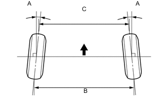
Bounce the vehicle at the corners up and down to stabilize the suspension and inspect toe-in.
Text in Illustration 
Front of Vehicle Toe-in (Unloaded Vehicle) Toe-in A: 0°2.6' +/-5' (0.04° +/-0.09°)
B - C: 1 +/-2 mm (0.04 +/-0.08 in.)
Tech Tips
If toe-in is not within the specified range, adjust it at the rack ends.
-
-
INSPECT WHEEL ANGLE (FRONT WHEEL ALIGNMENT)
-
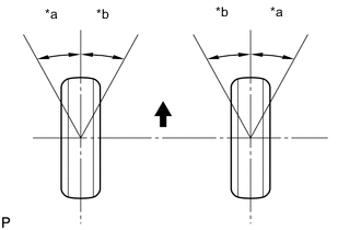
Text in Illustration *a Inside *b Outside Front of the vehicle Turn the steering wheel fully left and right and measure the turning angle.
If the right and left inside wheel angles differ from the specified range, check the right and left rack end lengths.
-
-
INSPECT CAMBER (REAR WHEEL ALIGNMENT)
-
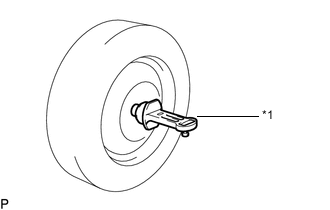
Text in Illustration *1 Gauge Install a camber-caster-kingpin gauge.
-
Inspect the camber.
If the measured value is not within the specified range, inspect the suspension parts for damage and wear. Replace parts as necessary because camber cannot be properly adjusted with any damaged or worn parts.
-
-
INSPECT TOE-IN (REAR WHEEL ALIGNMENT)
Text in Illustration Front of Vehicle If the toe-in is not within the specified range, inspect the suspension parts and replace if necessary.