FIT STANDARD / ADJUSTMENT METHOD ADJUSTMENT
-
INSPECT HOOD SUB-ASSEMBLY
-
Check that the clearance measurements of areas A to C are within the standard range.
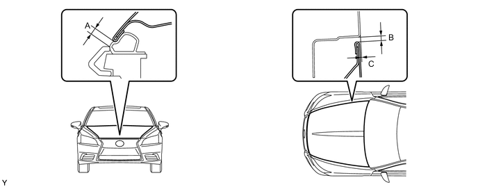
Area Specified Condition Area Specified Condition A 2.75 to 6.75 mm (0.108 to 0.266 in.) B 2.2 to 5.2 mm (0.0866 to 0.205 in.) C -1.5 to 1.5 mm (-0.0591 to 0.0591 in.) - - Tech Tips
Centering bolts are used to mount the hood hinge and hood lock. The hood and hood lock cannot be adjusted with the centering bolts on. Substitute the centering bolts with standard bolts (with washers) when making adjustments.
-
-
ADJUST HOOD SUB-ASSEMBLY
-
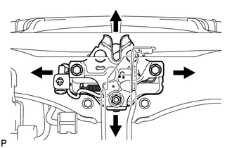
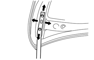
Adjust the hoods' position.
-
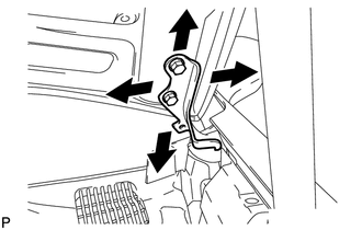
Loosen the hoods' 4 hinge bolts.
-
Move the hood and adjust the clearance between the hood and front fender.
-
Tighten the hoods' 4 hinge bolts after the adjustment.
- Torque:
- 13 N*m { 133 kgf*cm, 10 ft.*lbf }
-
-
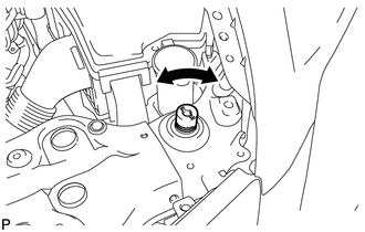
Adjust the cushion rubber so that the height of the hood and fender are aligned.
Tech Tips
Raise or lower the hood's front end by turning the cushion rubber.
-
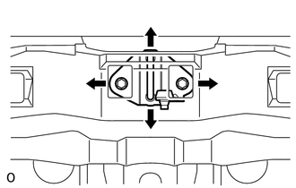
Adjust the hood lock.
-
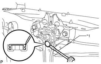
Text in Illustration *1 Protective Tape Using a screwdriver, remove the hood lock nut cap as shown in the illustration.
Tech Tips
Tape the screwdriver tip before use.
-
Loosen the 2 bolts and hood lock nut.
-
Adjust the hood lock position so that the striker can enter it smoothly.
-
Tighten the bolts and nut after the adjustment.
- Torque:
- 8.0 N*m { 82 kgf*cm, 71 in.*lbf }
-
Install a new hood lock nut cap.
-
-
-
INSPECT FRONT DOOR PANEL SUB-ASSEMBLY LH
-
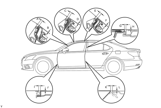
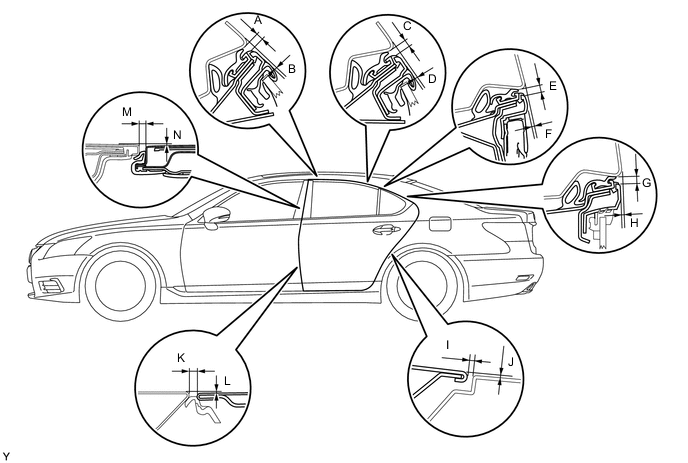
Check that the clearance measurements of areas A to L are within the standard range.
Tech Tips
-
Before adjusting the door position for vehicles equipped with side airbags and curtain shield airbags, be sure to disconnect the battery. After adjustment, inspect the SRS warning light, the side airbag system and the curtain shield airbag system for normal operation.
-
Use the same procedure for the RH and LH sides.
-
The procedure listed below is for the LH side.
-
Centering bolts are used to mount the hood hinge and hood lock. The hood and hood lock cannot be adjusted with the centering bolts on. Substitute the centering bolts with standard bolts (with washers) when making adjustments.
-
-
-
ADJUST FRONT DOOR
-
Disconnect the cable from the auxiliary battery negative (-) battery terminal.
CAUTION:
Wait at least 90 seconds after disconnecting the cable from the negative (-) auxiliary battery terminal to disable the SRS system.
Note
When disconnecting the cable, some systems need to be initialized after the cable is reconnected.
-
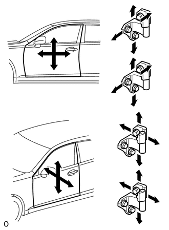
Using SST, loosen the body's hinge bolts and adjust the door's position.
- SST
- 09812-00010
-
Using SST, tighten the body's hinge bolts after the adjustment.
- Torque:
- 32.5 N*m { 332 kgf*cm, 24 ft.*lbf }
-
Loosen the door's hinge bolts and adjust the door's position.
-
Tighten the door's hinge bolts after the adjustment.
- Torque:
- 32.5 N*m { 332 kgf*cm, 24 ft.*lbf }
-
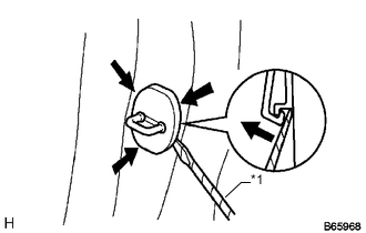
Text in Illustration *1 Protective Tape Using a screwdriver, detach the 4 claws and remove the cover.
Tech Tips
Tape the screwdriver tip before use.
-
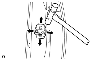
Using a T40 "TORX" socket, adjust the striker position by slightly loosening the striker mounting screws and hitting the striker with a plastic-faced hammer.
-
Using a T40 "TORX" socket, tighten the striker mounting screws after the adjustment.
- Torque:
- 23 N*m { 235 kgf*cm, 17 ft.*lbf }
-
Connect the auxiliary battery negative (-) terminal cable to the battery.
Note
When disconnecting the cable, some systems need to be initialized after the cable is reconnected.
-
Check SRS warning light.
-
-
INSPECT REAR DOOR PANEL SUB-ASSEMBLY LH
-
for Standard Body:
Check that the clearance measurements of areas A to N are within the standard range.
-
for Long Body:
Check that the clearance measurements of areas A to N are within the standard range.
Tech Tips
-
Before adjusting the door position for vehicles equipped with side airbags and curtain shield airbags, be sure to disconnect the battery. After adjustment, inspect the SRS warning light, the side airbag system and the curtain shield airbag system for normal operation.
-
Use the same procedure for the RH and LH sides.
-
The procedure listed below is for the LH side.
-
Centering bolts are used to mount the hood hinge and hood lock. The hood and hood lock cannot be adjusted with the centering bolts on. Substitute the centering bolts with standard bolts (with washers) when making adjustments.
-
-
ADJUST REAR DOOR
-
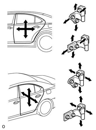
Loosen the body's hinge bolts and adjust the door's position.
-
Tighten the body's hinge bolts after the adjustment.
- Torque:
- 32.5 N*m { 332 kgf*cm, 24 ft.*lbf }
-
Loosen the door's hinge bolts and adjust the door's position.
-
Tighten the door's hinge bolts after the adjustment.
- Torque:
- 32.5 N*m { 332 kgf*cm, 24 ft.*lbf }
-
Text in Illustration *1 Protective Tape Using a screwdriver, detach the 4 claws and remove the cover.
Tech Tips
Tape the screwdriver tip before use.
-
Using a T40 "TORX" socket, adjust the striker position by slightly loosening the striker mounting screws and hitting the striker with a plastic-faced hammer.
-
Using a T40 "TORX" socket, tighten the striker mounting screws after the adjustment.
- Torque:
- 23 N*m { 235 kgf*cm, 17 ft.*lbf }
-
-
INSPECT LUGGAGE COMPARTMENT DOOR PANEL SUB-ASSEMBLY
-
Check that the clearance measurements of areas A to E are within the standard ranges.
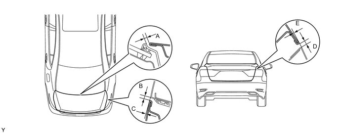
Tech Tips
Centering bolts are used to mount the door hinge to the vehicle body and door. The door cannot be adjusted with the centering bolts on. Substitute the centering bolts with standard bolts (w/ washers) when making adjustments.
-
-
ADJUST LUGGAGE COMPARTMENT DOOR PANEL SUB-ASSEMBLY
-
Horizontally and vertically adjust the door by loosening the door side hinge bolts.
- Torque:
- 8.0 N*m { 82 kgf*cm, 71 in.*lbf }
-
Remove the rear floor finish plate.
-
Adjust the striker position by slightly loosening the striker mounting screws and hitting the striker with a plastic-faced hammer.
-
Tighten the striker mounting screws after the adjustment.
- Torque:
- 5.5 N*m { 56 kgf*cm, 49 in.*lbf }
-