FRONT FENDER APRON ASSEMBLY REPLACEMENT
-
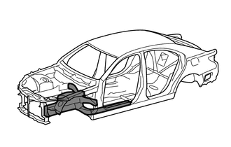
With the radiator support and front body pillar lower gusset removed.
-
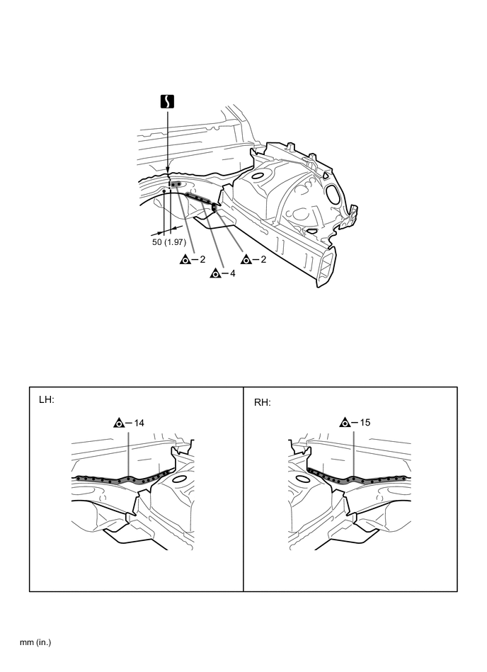
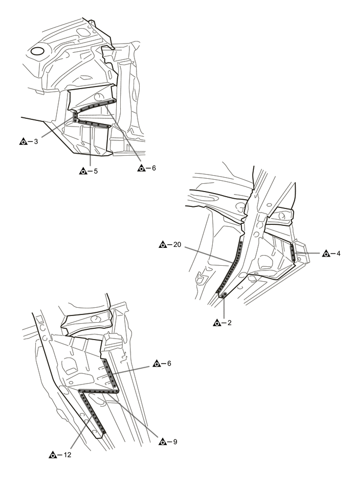
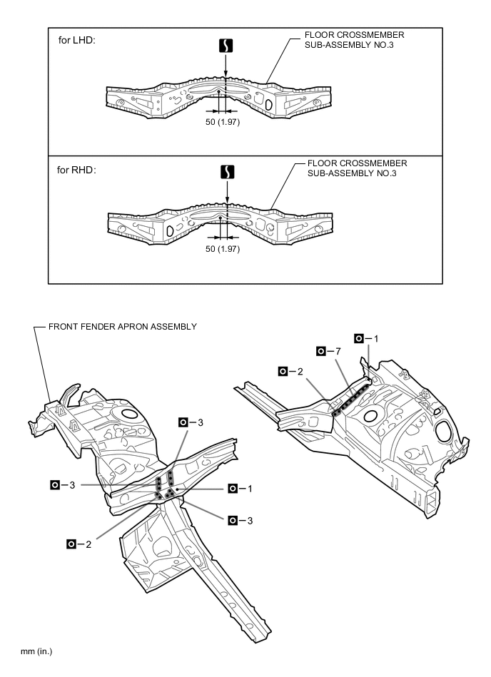
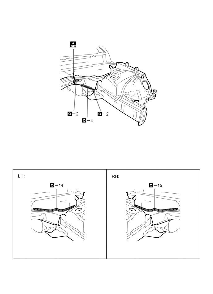
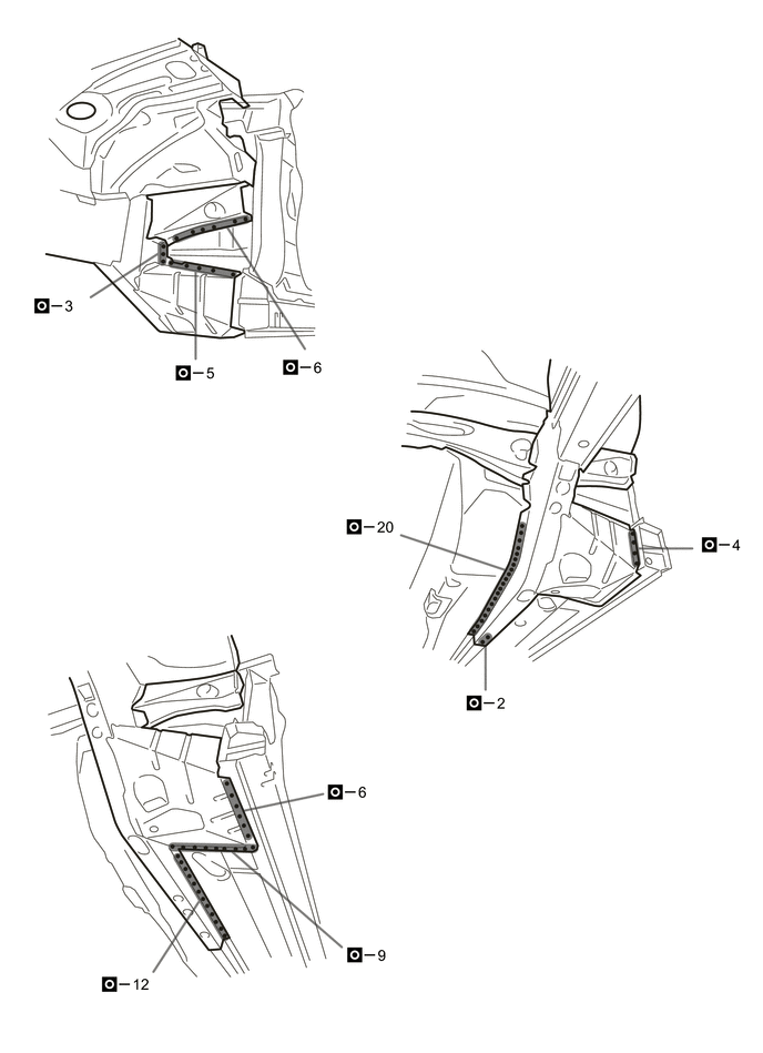
REMOVAL
Symbol Meaning 
Remove Weld Points 
Remove Weld Points 
Remove Weld Points 
Cut with Disc Sander etc. 
Cut and Join Location
-
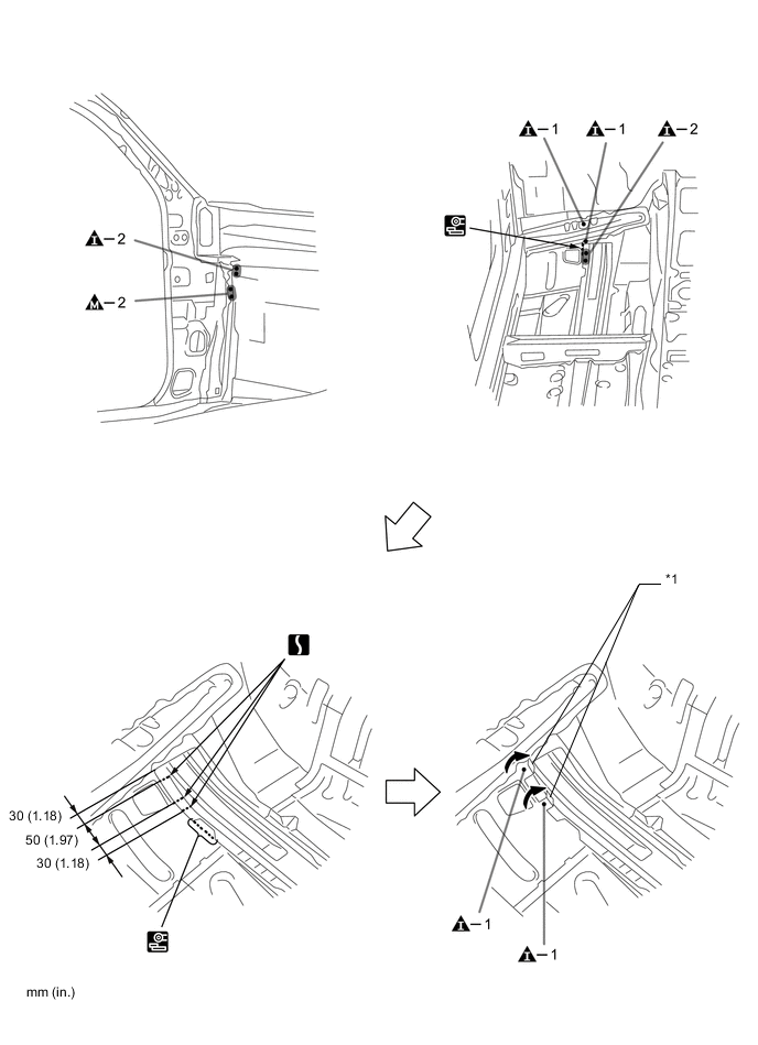
Bend in the same way as *1.
REMOVAL POINT
-
-
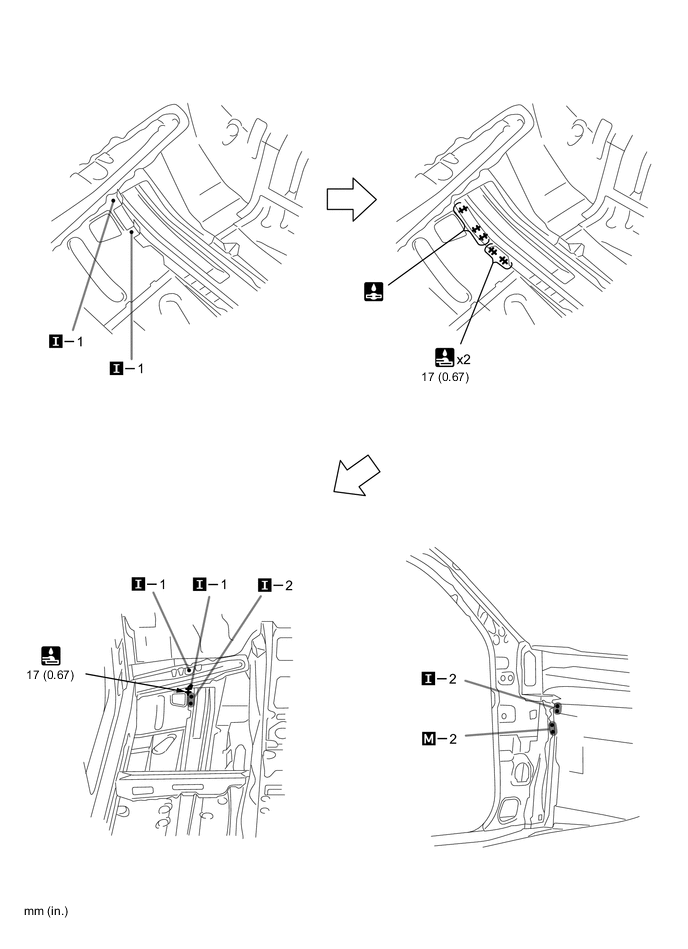
INSTALLATION
Symbol Meaning 
Plug Weld 
Plug Weld 
Plug Weld Cut and Join Location 
Fillet Weld 
Butt Weld
-
Inspect the fitting of the related parts around the new parts before welding. This affects the appearance of the finish.
-
Temporarily install the new parts and measure each part of the new parts in accordance with the body dimension diagram. (See the body dimensions)
-
Make sure to attach correctly in accordance with the body dimension diagram as this part affects the front wheel alignment.
-
Before temporarily installing the new parts, weld the floor crossmember sub-assembly No.3 and front fender apron assembly with the standard number of welding points.
-
After welding, apply body sealer and undercoating to the corresponding parts. (See the painting / coating)
-
After applying the top coat, apply anti-rust agent to the internal panel portion of the closed section structural weld points.
INSTALLATION POINT
-