FRAME TWO-DIMENSIONAL DISTANCE
-
Upper Face
Tech Tips
For symbols, capital letters indicate right side of vehicle, small letters indicate left side of vehicle (seen from rear).
Measuring Point Name Symbol Name Hole Diameter
mm (in.)
A, a Front bamper extension No. 2 installation bolt M10 (0.39) B, b No. 1 body mounting hole φ26 (1.02) C, c Front spring support hole φ12.2 (0.480) D, d No. 2 body mounting hole φ43 (1.69) E, e Side rail inner channel standard hole 16X16 (0.63X0.63) F, f No. 3 body mounting hole φ43 (1.69) G, g No. 4 body mounting hole φ43 (1.69) 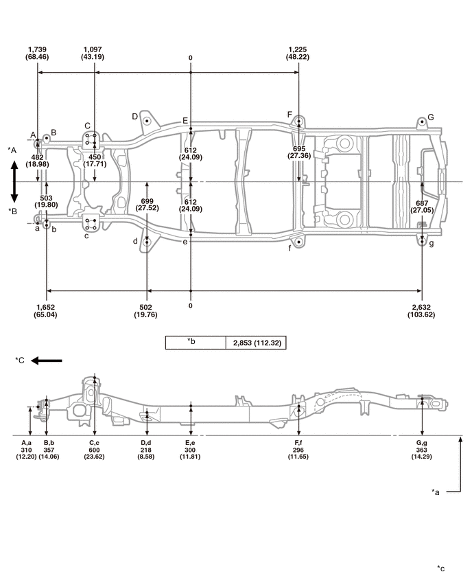
*A RH *B LH *C Front - - *a Imaginary Datum Line *b Wheel base *c mm
(in.)
- - -
Lower Face
Tech Tips
For symbols, capital letters indicate right side of vehicle, small letters indicate left side of vehicle (seen from rear).
Measuring Point Name Symbol Name Hole Diameter
mm (in.)
A, a Front bamper extension No. 2 installation bolt M10 (0.39) B, b Front stabilizer bracket installation nut M12 (0.47) C, c Suspension lower arm installation hole - rear 42 X24 (1.65X0.94) D, d Suspension lower arm installation hole - front 36.5X18.5 (1.437X0.728) E, e Side rail inner channel standard hole 16X16 (0.63X0.63) F, f Lower control arm installation hole - inner φ16.5 (0.650) G, g Upper control arm installation hole - inner φ14.5 (0.571) H, h Rear shock absorber installation hole φ29.5 (1.161) I Lateral control rod installation hole - front φ15 (0.59) J, j Transport hook installation nut M12 (0.47) 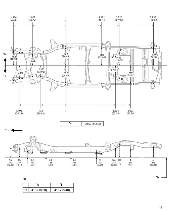
*A RH *B LH *C Front - - *b Imaginary Datum Line *c Wheel base *d Vehicle Dimensions *e Heavy Duty *f Light Duty *g mm
(in.)
-
Upper Face (w/ Kinetic Dynamic Suspension System)
Tech Tips
For symbols, capital letters indicate right side of vehicle, small letters indicate left side of vehicle (seen from rear).
Measuring Point Name Symbol Name Hole Diameter
mm (in.)
A, a Front bamper extension No. 2 installation bolt M10 (0.39) B, b No. 1 body mounting hole φ26 (1.02) C, c Front spring support hole φ12.2 (0.480) D, d No. 2 body mounting hole φ43 (1.69) E, e Side rail inner channel standard hole 16X16 (0.63X0.63) F, f No. 3 body mounting hole φ43 (1.69) G, g No. 4 body mounting hole φ43 (1.69) 
*A RH *B LH *C Front - - *a Imaginary Datum Line *b Wheel base *c mm
(in.)
- - -
Lower Face (w/ Kinetic Dynamic Suspension System)
Tech Tips
For symbols, capital letters indicate right side of vehicle, small letters indicate left side of vehicle (seen from rear).
Measuring Point Name Symbol Name Hole Diameter
mm (in.)
A, a Front bamper extension No. 2 installation bolt M10 (0.39) B, b Front stabilizer bracket installation nut M12 (0.47) C, c Kinetic Dynamic Suspension System bracket installation hole φ18.5 (0.728) D, d Suspension lower arm installation hole - rear 42X24(1.65X0.94) E, e Suspension lower arm installation hole - front 36.5X18.5 (1.437X0.728) F, f Side rail inner channel standard hole 16X16(0.63X0.63) G, g Lower control arm installation hole - inner φ16.5 (0.650) H, h Upper control arm installation hole - inner φ14.5 (0.571) I, i Rear shock absorber installation hole φ29.5 (1.161) J Lateral control rod installation hole - front φ15 (0.59) K, k Transport hook installation nut M12 (0.47) 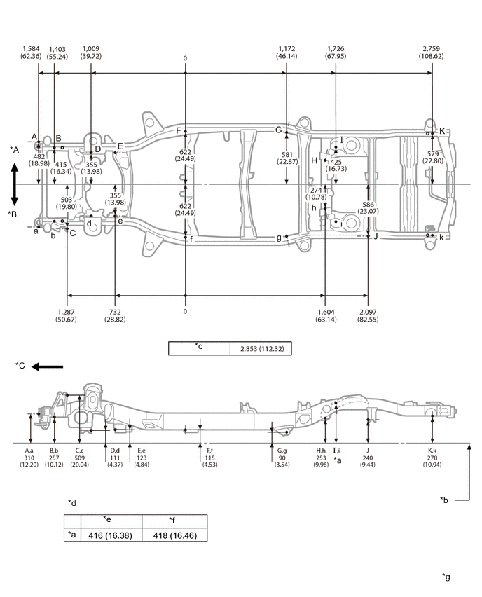
*A RH *B LH *C Front - - *b Imaginary Datum Line *c Wheel base *d Vehicle Dimensions *e Heavy Duty *f Light Duty *g mm
(in.)
-
Upper Face (w/ Winch)
Tech Tips
For symbols, capital letters indicate right side of vehicle, small letters indicate left side of vehicle (seen from rear).
Measuring Point Name Symbol Name Hole Diameter
mm (in.)
A, a Winch bracket installation nut M12 (0.47) B, b No. 1 body mounting hole φ26 (1.02) C, c Front spring support hole φ12.2 (0.480) D, d No. 2 body mounting hole φ43 (1.69) E, e Side rail inner channel standard hole 16X16 (0.63X0.63) F, f No. 3 body mounting hole φ43 (1.69) G, g No. 4 body mounting hole φ43 (1.69) 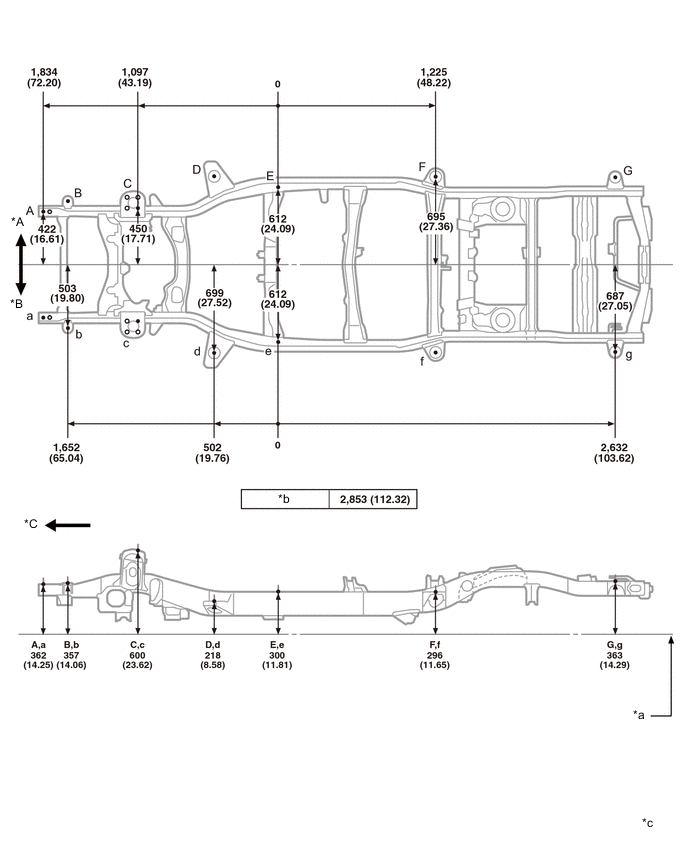
*A RH *B LH *C Front - - *a Imaginary Datum Line *b Wheel base *c mm
(in.)
- - -
Lower Face (w/ Winch)
Tech Tips
For symbols, capital letters indicate right side of vehicle, small letters indicate left side of vehicle (seen from rear).
Measuring Point Name Symbol Name Hole Diameter
mm (in.)
A, a Winch bracket installation nut M12 (0.47) B, b Front stabilizer bracket installation nut M12 (0.47) C, c Suspension lower arm installation hole - rear 42X24 (1.65X0.94) D, d Suspension lower arm installation hole - front 36.5X18.5 (1.437X0.728) E, e Side rail inner channel standard hole 16X16 (0.63X0.63) F, f Lower control arm installation hole - inner φ16.5 (0.650) G, g Upper control arm installation hole - inner φ14.5 (0.571) H, h Rear shock absorber installation hole φ29.5 (1.161) I Lateral control rod installation hole - front φ15 (0.59) J, j Transport hook installation nut M12 (0.47) 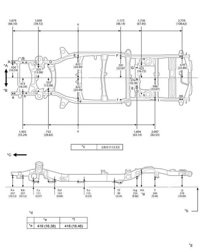
*A RH *B LH *C Front - - *b Imaginary Datum Line *c Wheel base *d Vehicle Dimensions *e Heavy Duty *f Light Duty *g mm
(in.)