ENGINE COMPARTMENT THREE-DIMENSIONAL DISTANCE
Tech Tips
For symbols, capital letters indicate right side of vehicle, small letters indicate left side of vehicle (seen from rear).
| Symbol | Name | Hole Diameter mm (in.) |
|---|---|---|
| A, a | Front fender installation nut | M6 (0.24) |
| B, b | Front fender installation nut | M6 (0.24) |
| C, c | Front fender installation nut | M6 (0.24) |
| D | Cowl panel center mark | - |
| E, e | Front fender No. 2 side apron standard hole | φ10 (0.39) |
| F, f | Radiator upper support installation nut | M6 (0.24) |
| G | Hood lock support brace installation nut | M6 (0.24) |
| H, h | Radiator support standard hole | φ10 (0.39) |
| I, i | Radiator support standard hole | φ10 (0.39) |
| J, j | Front fender apron standard hole | φ15 (0.59) |
| K, k | Front fender bracket standard hole | φ10 (0.39) |
| L, l | Hood hinge installation nut | M8 (0.31) |
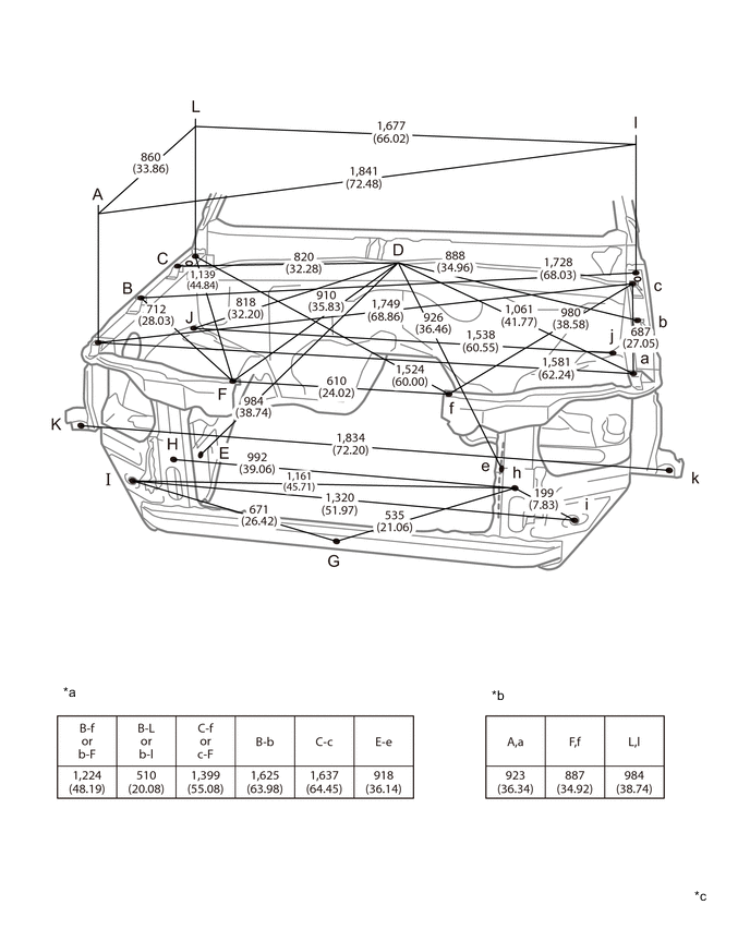
| *a | Vehicle Dimensions | *b | Height from Imaginary Datum Line |
| *c | mm (in.) |
- | - |