FIT STANDARD / ADJUSTMENT METHOD ADJUSTMENT
-
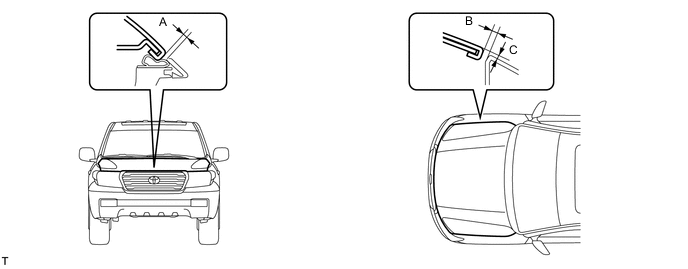
INSPECT HOOD
-
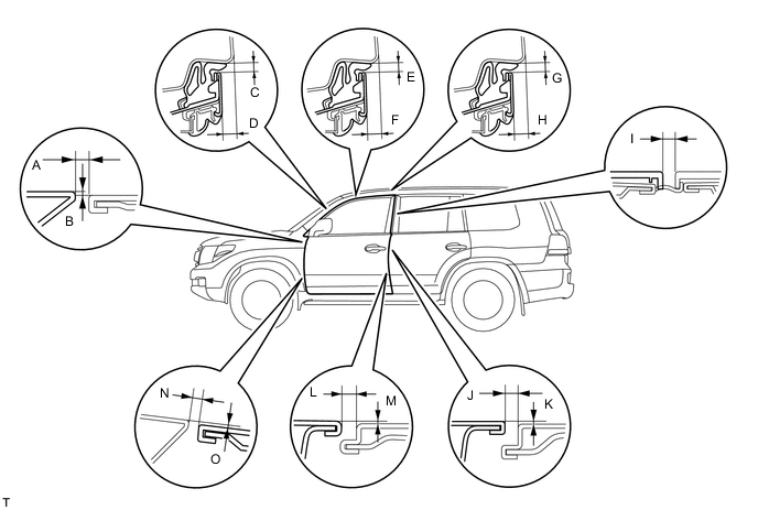
Check that the clearance measurements of areas A to C are within the standard range.
Tech Tips
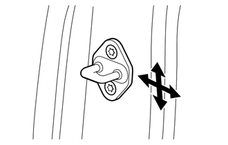
Centering bolts are used to mount the hood hinge and hood lock. The hood and hood lock cannot be adjusted with the centering bolts on. Substitute the centering bolts with standard bolts (with washers) when making adjustments.
-
-
ADJUST HOOD
-
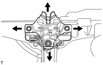
Adjust the hood position.
-
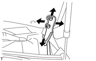
Loosen the 4 hinge bolts of the hood.
-
Move the hood and adjust the clearance between the hood and front fender.
-
Tighten the 4 hinge bolts of the hood after the adjustment.
- Torque:
- 13 N*m { 133 kgf*cm, 10 ft.*lbf }
-
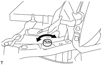
Adjust the cushion rubber so that the height of the hood and fender are aligned.
Tech Tips
Raise or lower the hood front end by turning the cushion rubber.
-
-
Adjust the hood lock.
-
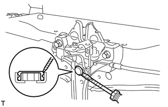
Using a screwdriver, remove the hood lock nut cap as shown in the illustration.
Tech Tips
Tape the screwdriver tip before use.
-
Loosen the 2 bolts and hood lock nut.
-
Adjust the hood lock position so that the striker can enter it smoothly.
-
Tighten the bolts and nut after the adjustment.
- Torque:
- 5.5 N*m { 56 kgf*cm, 49 in.*lbf }
-
Install a new cap.
-
-
-
INSPECT FRONT DOOR
-
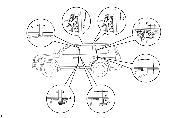
Check that the clearance measurements of areas A to O are within the standard range.
Tech Tips
-
Before adjusting the door position for vehicles equipped with side airbags and curtain shield airbags, be sure to disconnect the cable from the negative (-) battery terminal.
-
Use the same procedures for the RH side and LH side.
-
The procedures listed below are for the LH side.
-
Centering bolts are used to mount the door hinge to the vehicle body and door. The door cannot be adjusted with the centering bolts on. Substitute the centering bolts with standard bolts (with washers) when making adjustments.
-
-
-
ADJUST FRONT DOOR
-
Disconnect the cable from the negative (-) battery terminal.
CAUTION:
Wait at least 90 seconds after disconnecting the cable from the negative (-) battery terminal to disable the SRS system.
Note
When disconnecting the cable, some systems need to be initialized after the cable is reconnected.
-
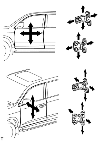
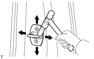
Using SST, loosen the body hinge bolts and adjust the door position.
- SST
- 09812-00010
-
Using SST, tighten the body hinge bolts after the adjustment.
- Torque:
- 26 N*m { 265 kgf*cm, 19 ft.*lbf }
-
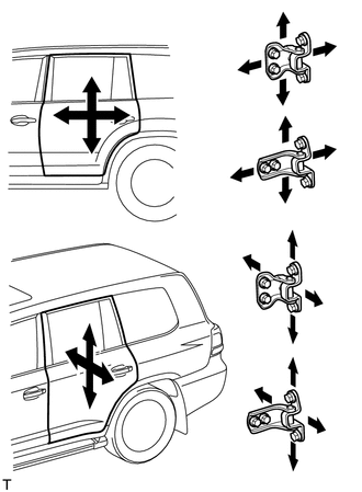
Loosen the door hinge bolts and adjust the door position.
-
Tighten the door hinge bolts after the adjustment.
- Torque:
- 26 N*m { 265 kgf*cm, 19 ft.*lbf }
-
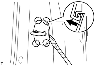
Using a screwdriver, detach the 4 claws and remove the cover.
Tech Tips
Tape the screwdriver tip before use.
-

Using a T40 "TORX" socket, adjust the striker position by slightly loosening the striker mounting screws and hitting the striker with a plastic-faced hammer.
-
Using a T40 "TORX" socket, tighten the striker mounting screws after the adjustment.
- Torque:
- 23 N*m { 235 kgf*cm, 17 ft.*lbf }
-
Attach the 4 claws to install the cover.
-
Connect the cable to the negative (-) battery terminal.
Note
When disconnecting the cable, some systems need to be initialized after the cable is reconnected.
-
Check the SRS warning light.
-
-
INSPECT REAR DOOR
-
Check that the clearance measurements of areas A to M are within the standard range.
Tech Tips
-
Before adjusting the door position for vehicles equipped with side airbags and curtain shield airbags, be sure to disconnect the cable from the negative (-) battery terminal.
-
Use the same procedures for the RH side and LH side.
-
The procedures listed below are for the LH side.
-
Centering bolts are used to mount the door hinge to the vehicle body and door. The door cannot be adjusted with the centering bolts on. Substitute the centering bolts with standard bolts (with washers) when making adjustments.
-
-
-
ADJUST REAR DOOR
-
Loosen the body hinge bolts and adjust the door position.
- SST
- 09812-00010
-
Tighten the body hinge bolts after the adjustment.
- Torque:
- 26 N*m { 265 kgf*cm, 19 ft.*lbf }
-
Loosen the door hinge bolts and adjust the door position.
-
Tighten the door hinge bolts after the adjustment.
- Torque:
- 26 N*m { 265 kgf*cm, 19 ft.*lbf }
-
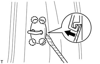
Using a screwdriver, detach the 4 claws and remove the cover.
Tech Tips
Tape the screwdriver tip before use.
-
Using a T40 "TORX" socket, adjust the striker position by slightly loosening the striker mounting screws and hitting the striker with a plastic-faced hammer.
-
Using a T40 "TORX" socket, tighten the striker mounting screws after the adjustment.
- Torque:
- 23 N*m { 235 kgf*cm, 17 ft.*lbf }
-
Attach the 4 claws to install the cover.
-
-
INSPECT TAIL GATE PANEL
-
Check that the clearance measurements of areas H to I are within the standard range.
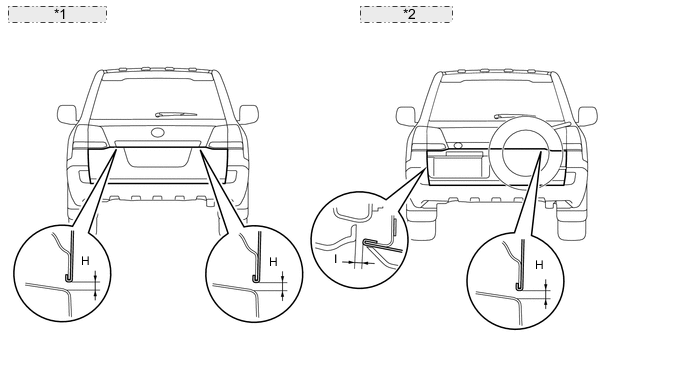
*1 w/o Tire Carrier: *2 w/ Tire Carrier:
-
-
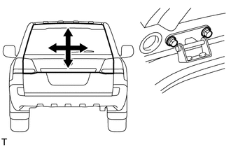
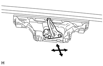
ADJUST TAIL GATE PANEL
-
Loosen the hinge bolts.
-
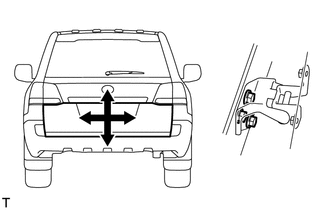
Adjust the tail gate by moving it up and down and left and right so that the dimensions are within the specified range.
-
Tighten the hinge bolts.
- Torque:
- 28 N*m { 286 kgf*cm, 21 ft.*lbf }
-
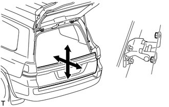
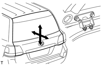
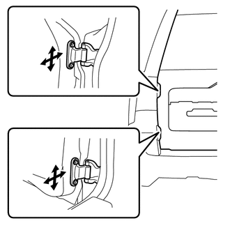
Loosen the hinge bolts.
-
Adjust the tail gate by moving it up and down and forward and backward so that the dimensions are within the specified range.
-
Tighten the hinge bolts.
- Torque:
- 31 N*m { 316 kgf*cm, 23 ft.*lbf }
-
-
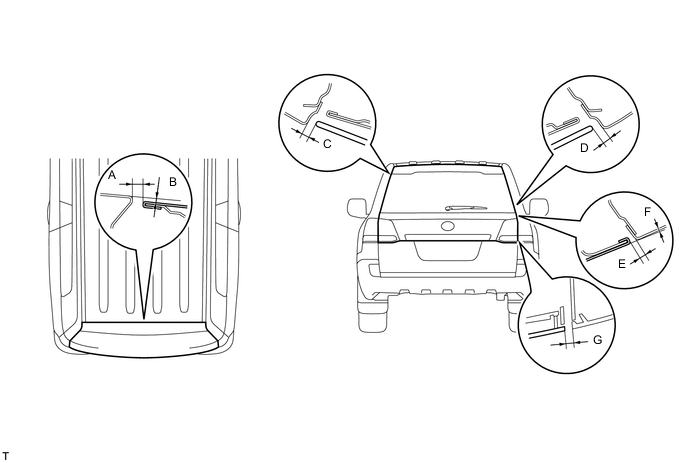
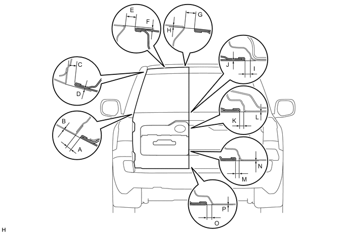
INSPECT BACK DOOR PANEL
-
Check that the clearance measurements of areas A to G are within the standard range.
-
-
ADJUST BACK DOOR PANEL
-
Loosen the hinge bolts.
-
Adjust the back door by moving it up and down and left and right so that the dimensions are within the specified range.
-
Tighten the hinge bolts.
- Torque:
- 19 N*m { 194 kgf*cm, 14 ft.*lbf }
-
Partially remove the roof headlining.
-
Loosen the hinge nuts.
-
Adjust the back door by moving it up and down and forward and backward so that the dimensions are within the specified range.
-
Tighten the hinge nuts.
- Torque:
- 19 N*m { 194 kgf*cm, 14 ft.*lbf }
-
Install the roof headlining.
-
-
INSPECT BACK DOOR PANEL RH (for RH Side)
-
Check that the clearance measurements of areas A to P are within the standard ranges.
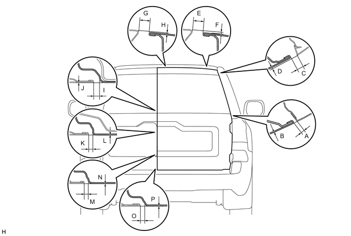
Note
Centering bolts are used to mount the door hinge to the vehicle body and door. The door cannot be adjusted with the centering bolts on. Substitute the centering bolts for standard bolts when making adjustments.
-
-
ADJUST BACK DOOR PANEL RH (for RH Side)
-
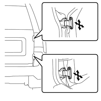
Loosen the hinge bolts on the back door panel and adjust the back door panel position.
-
Tighten the hinge bolts on the back door panel after the adjustment.
- Torque:
- 31 N*m { 316 kgf*cm, 23 ft.*lbf }
-
Adjust the back door lock striker position by slightly loosening the bolts and hitting the back door lock striker with a plastic-faced hammer.
-
Tighten the bolts after the adjustment.
- Torque:
- 29 N*m { 296 kgf*cm, 21 ft.*lbf }
-
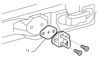
Using a T40 "TORX" socket wrench, remove the 2 bolts and striker.
-
Select a back door lock striker shim so that the clearance measurements are within the specified range.
Tech Tips
There are 2 types of back door lock striker shims (0.5 mm and 2.0 mm).
Text in Illustration *1 Back Door Lock Striker Shim -
Using a T40 "TORX" socket wrench, install the striker with the 2 bolts.
Tech Tips
Mark sure that the yellow marking is facing up when installing the striker.
- Torque:
- 23 N*m { 235 kgf*cm, 17 ft.*lbf }
-
-
INSPECT BACK DOOR PANEL LH (for LH Side)
-
Check that the clearance measurements of areas A to P are within the standard ranges.
-
-
ADJUST BACK DOOR PANEL LH (for LH Side)
-
Loosen the hinge bolts on the back door panel and adjust the back door panel position.
-
Tighten the hinge bolts on the back door panel after the adjustment.
- Torque:
- 31 N*m { 316 kgf*cm, 23 ft.*lbf }
-
Using a T40 "TORX" socket, adjust the back door lock striker plate position by slightly loosening the bolts and hitting the back door lock striker plate with a plastic-faced hammer.
-
Using a T40 "TORX" socket, tighten the bolts after the adjustment.
- Torque:
- 23 N*m { 235 kgf*cm, 17 ft.*lbf }
-