REAR FLOOR PAN CUT AND JOIN REPLACEMENT SECTIONS
-
With the rear floor rear cross outer panel and rear floor crossmember upper guest removed.
-
REMOVAL
Symbol Meaning 
Remove Weld Points 
Remove Weld Points 
Cut Location 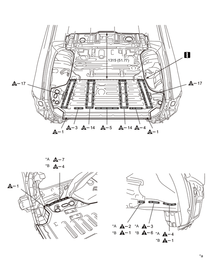
*A LH *B RH *a mm (in.) - - -
INSTALLATION
Symbol Meaning 
Plug Weld 
Plug Weld Cut Location 
Body Sealer
-
Cut the new part so that it overlaps the previous cut location by approximately 20 mm (0.79 in).
-
Before temporarily installing the new parts, weld the belt anchor No. 4 reinforcement and flexible hose mounting bracket with the standard number of welding points.
-
Temporarily install the new parts and measure each part of the new parts in accordance with the body dimension diagram. (See the body dimension diagram)
-
*a: Perform plug-welding in the area where the panel are overlapped. Apply body sealer to both sides of each
Tech Tips
-
Confirm that the panels are securely welded together.
-
Apply sealer in an even, continuous bead.
-
-
After welding, apply body sealer and undercoating to the corresponding parts. (See the painting / coating)
-
After applying the top coat, apply anti-rust agent to the internal panel portion of the closed section structural weld points.
INSTALLATION POINT
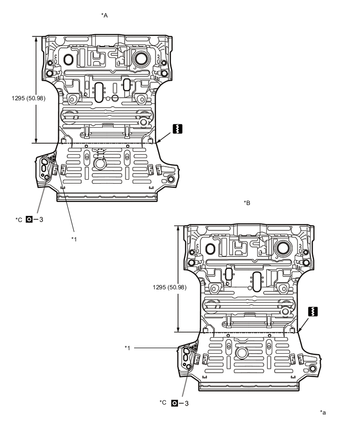
*A LHD B RHD *C w/ Rear No. 2 Seat (except Face to Face Seat Type) - - *1 Belt Anchor No. 4 Reinforcement - - *a mm (in.) - - 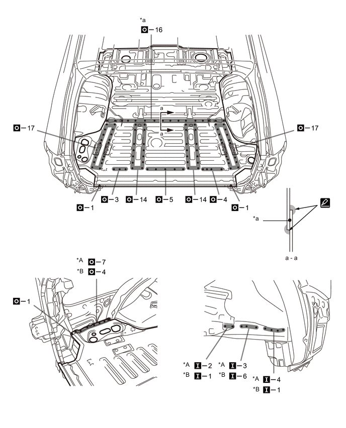
*A LH *B RH -