FIT STANDARD / ADJUSTMENT METHOD ADJUSTMENT
-
INSPECT HOOD SUB-ASSEMBLY
-
Check that the clearance measurements of areas *a through *e are within each standard range.
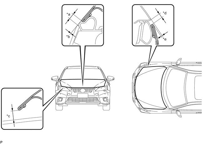
Standard Clearance Area Measurement Area Measurement *a 3.3 to 7.3 mm (0.130 to 0.287 in.) *b -1.5 to 1.5 mm (-0.0591 to 0.0591 in.) *c 5.65 to 9.65 mm (0.222 to 0.380 in.) *d 2.5 to 5.5 mm (0.0984 to 0.217 in.) *e -0.6 to 2.4 mm (-0.0236 to 0.0945 in.) - - Tech Tips
Centering bolts are used to mount the hood hinge and hood lock. The hood and hood lock cannot be adjusted with the centering bolts installed. Substitute the centering bolts with standard bolts when making adjustments.
-
-
ADJUST HOOD SUB-ASSEMBLY
-
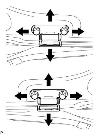
Horizontally and vertically adjust the hood.
-
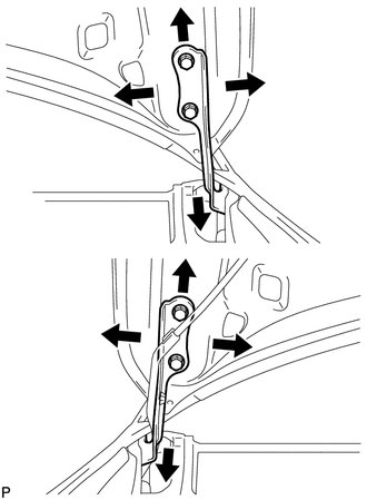
Loosen the 4 hinge bolts of the hood.
-
Adjust the clearance between the hood and front fender by moving the hood.
-
Tighten the 4 hinge bolts after the adjustment.
- Torque:
- 13 N*m { 133 kgf*cm, 10 ft.*lbf }
-
-
Adjust the height of the front end of the hood using the cushion rubbers.
-
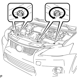
Adjust the 4 cushion rubbers so that the heights of the hood and fender are aligned.
Tech Tips
Raise or lower the front end of the hood by turning the 4 cushion rubbers.
-
-
Remove the radiator support opening cover.
-
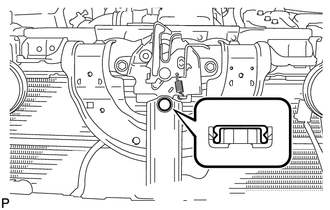
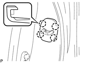
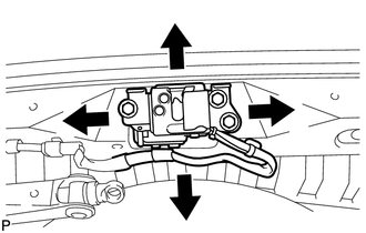
Adjust the hood lock.
-
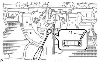
Text in Illustration *1 Protective Tape Using a screwdriver, remove the hood lock nut cap.
Tech Tips
Tape the screwdriver tip before use.
-

Text in Illustration *1 Hood Lock Bolt Loosen the 2 bolts and hood lock bolt.
-
Adjust the hood lock and tighten the 2 bolts and hood lock bolt.
- Torque:
- 8.0 N*m { 82 kgf*cm, 71 in.*lbf }
-
Check that the striker can engage with the hood lock smoothly.
-
-
Install a new hood lock nut cap.
-
Install the radiator support opening cover.
-
-
INSPECT FRONT DOOR
-
Check that the clearance measurements of areas *a through *p are within each standard range.

Standard Clearance Area Measurement Area Measurement *a 3.35 to 6.35 mm (0.132 to 0.250 in.) *b 2.5 to 5.5 mm (0.0984 to 0.217 in.) *c 3.35 to 6.35 mm (0.132 to 0.250 in.) *d 1.0 to 4.0 mm (0.0394 to 0.157 in.) *e 3.35 to 6.35 mm (0.132 to 0.250 in.) *f 1.0 to 4.0 mm (0.0394 to 0.157 in.) *g 3.0 to 6.0 mm (0.118 to 0.236 in.) *h -1.5 to 1.5 mm (-0.0591 to 0.0591 in.) *i 2.7 to 5.7 mm (0.106 to 0.224 in.) *j -1.5 to 1.5 mm (-0.0591 to 0.0591 in.) *k 3.65 to 6.65 mm (0.144 to 0.262 in.) *l 3.65 to 6.65 mm (0.144 to 0.262 in.) *m 2.5 to 5.5 mm (0.0984 to 0.217 in.) *n -1.5 to 1.5 mm (-0.0591 to 0.0591 in.) *o 2.5 to 5.5 mm (0.0984 to 0.217 in.) *p -1.5 to 1.5 mm (-0.0591 to 0.0591 in.) CAUTION:
Before adjusting the door positions of vehicles equipped with side and curtain shield airbags, be sure to disconnect the battery. After adjustment, check that the SRS warning light is operating normally and there are no SRS DTCs output.
Tech Tips
-
Use the same procedure for the RH side and LH side.
-
The procedure listed below is for the LH side.
-
Centering bolts are used to mount the door hinge to the vehicle body and door. The door cannot be adjusted with the centering bolts installed on it. Substitute the centering bolts with standard bolts when making adjustments.
-
Specified torque for standard bolts is shown in the standard bolt chart.
-
-
-
ADJUST FRONT DOOR
Note
Make sure that the power switch is off or on (ACC) when adjusting door lock strikers.
-
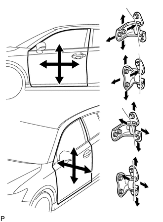
Using SST, loosen the hinge bolts on the vehicle body and adjust the door position.
- SST
- 09812-00010
-
Tighten the hinge bolts on the vehicle body after the adjustment.
- Torque:
- 26 N*m { 265 kgf*cm, 19 ft.*lbf }
-
Loosen the hinge bolts on the door and adjust the door position.
-
Tighten the hinge bolts on the door after the adjustment.
- Torque:
- 27 N*m { 275 kgf*cm, 20 ft.*lbf }
-
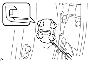
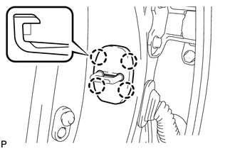
Text in Illustration *1 Protective Tape Using a screwdriver, disengage the 4 claws and remove door lock striker cover.
Tech Tips
Tape the screwdriver tip before use.
-
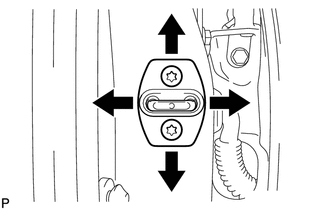
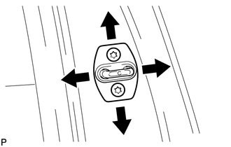
Using a T40 "TORX" socket wrench, slightly loosen the striker mounting screws.
-
Using a brass bar and a hammer, hit the striker to adjust its position.
-
Using a T40 "TORX" socket wrench, tighten the striker mounting screws after adjustment.
- Torque:
- 23 N*m { 235 kgf*cm, 17 ft.*lbf }
-
Engage the 4 claws and install the door lock striker cover.
-
-
INSPECT REAR DOOR
-
Check that the clearance measurements of areas *a through *r are within each standard range.
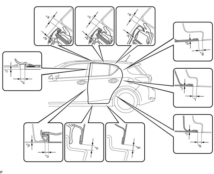
Standard Clearance Area Measurement Area Measurement *a 3.35 to 6.35 mm (0.132 to 0.250 in.) *b 1.5 to 4.5 mm (0.0591 to 0.177 in.) *c 3.35 to 6.35 mm (0.132 to 0.250 in.) *d 1.5 to 4.5 mm (0.0591 to 0.177 in.) *e 3.35 to 6.35 mm (0.132 to 0.250 in.) *f 0.8 to 3.8 mm (0.0315 to 0.150 in.) *g 2.5 to 5.5 mm (0.0984 to 0.217 in.) *h -1.5 to 1.5 mm (-0.0591 to 0.0591 in.) *i 2.5 to 5.5 mm (0.0984 to 0.217 in.) *j -1.5 to 1.5 mm (-0.0591 to 0.0591 in.) *k 2.5 to 5.5 mm (0.0984 to 0.217 in.) *l -1.5 to 1.5 mm (-0.0591 to 0.0591 in.) *m 3.65 to 6.65 mm (0.144 to 0.262 in.) *n 3.65 to 6.65 mm (0.144 to 0.262 in.) *o 2.7 to 5.7 mm (0.106 to 0.224 in.) *p -1.5 to 1.5 mm (-0.0591 to 0.0591 in.) *q 3.0 to 6.0 mm (0.118 to 0.236 in.) *r -1.5 to 1.5 mm (-0.0591 to 0.0591 in.) CAUTION:
Before adjusting the door positions of vehicles equipped with side and curtain shield airbags, be sure to disconnect the battery. After adjustment, check that the SRS warning light is operating normally and there are no SRS DTCs output.
Tech Tips
-
Use the same procedure for the RH side and LH side.
-
The procedure listed below is for the LH side.
-
Centering bolts are used to mount the door hinge to the vehicle body and door. The door cannot be adjusted with the centering bolts installed. Substitute the centering bolts with standard bolts when making adjustments.
-
Specified torque for standard bolts is shown in the standard bolt chart.
-
-
-
ADJUST REAR DOOR
Note
Make sure that the power switch is off or on (ACC) when adjusting door lock strikers.
-

Using SST, loosen the hinge bolts on the vehicle body and adjust the door position.
- SST
- 09812-00010
-
Tighten the hinge bolts on the vehicle body after the adjustment.
- Torque:
- 26 N*m { 265 kgf*cm, 19 ft.*lbf }
-
Loosen the hinge bolts on the door and adjust the door position.
-
Tighten the hinge bolts on the door after the adjustment.
- Torque:
- 27 N*m { 275 kgf*cm, 20 ft.*lbf }
-
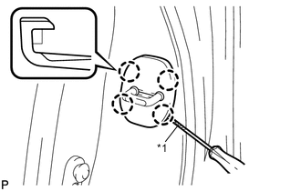
Text in Illustration *1 Protective Tape Using a screwdriver, disengage the 4 claws and remove door lock striker cover.
Tech Tips
Tape the screwdriver tip before use.
-
Using a T40 "TORX" socket wrench, slightly loosen the striker mounting screws.
-
Using a brass bar and a hammer, hit the striker to adjust its position.
-
Using a T40 "TORX" socket wrench, tighten the striker mounting screws after adjustment.
- Torque:
- 23 N*m { 235 kgf*cm, 17 ft.*lbf }
-
Engage the 4 claws and install the door lock striker cover.
-
-
INSPECT BACK DOOR
-
Check that the clearance measurements of areas *a through *l are within each standard range.

Standard Clearance Area Measurement Area Measurement *a 5.2 to 8.2 mm (0.205 to 0.323 in.) *b 0 to 3.0 mm (0 to 0.118 in.) *c 5.2 to 8.2 mm (0.205 to 0.323 in.) *d 4.0 to 7.0 mm (0.157 to 0.276 in.) *e 1.2 to 4.2 mm (0.0472 to 0.165 in.) *f 4.0 to 7.0 mm (0.157 to 0.276 in.) *g 1.1 to 4.7 mm (0.0433 to 0.185 in.) *h 3.25 to 7.25 mm (0.128 to 0.285 in.) *i -1.5 to 1.5 mm (-0.0591 to 0.0591 in.) *j 3.2 to 7.2 mm (0.126 to 0.283 in.) *k -1.8 to 2.2 mm (-0.0709 to 0.0866 in.) *l 3.85 to 5.85 mm (0.152 to 0.230 in.) Tech Tips
Centering bolts are used to mount the door hinge to the vehicle body and door. The door cannot be adjusted with the centering bolts installed. Substitute the centering bolts with standard bolts (with washers) when making adjustments.
-
-
ADJUST BACK DOOR
-
Before adjusting the upper end of the back door up and down or left and right, loosen the bolts.
-
Tighten the body side hinge after the adjustment.
- Torque:
- 19 N*m { 194 kgf*cm, 14 ft.*lbf }
-
Loosen the 3 bolts.
-
Tighten the bolts after the adjustment.
- Torque:
- 7.5 N*m { 76 kgf*cm, 66 in.*lbf }
-