UNDER BODY TWO-DIMENSIONAL DISTANCE
Tech Tips
-
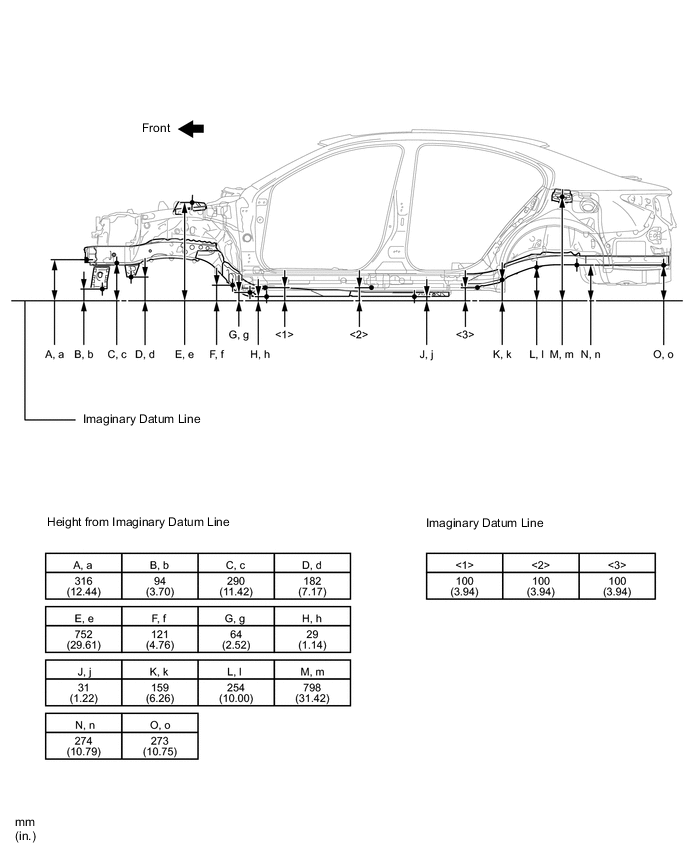
Length measurements are indicated at the points where the arrows extending from the zero point intersect the lines that extend towards the outside of the illustration from each point.
-
In cases in which only one dimension is given, left and right are symmetrical.
-
For symbols, capital letters indicate right side of vehicle, small letters indicate left side of vehicle (seen from rear).
| Symbol | Name | Hole Diameter mm (in.) |
|---|---|---|
| A, a | Front Bumper Reinforcement Installation Nut | M10 (0.39) |
| B, b | Front Crossmember Standard Hole | φ13 (0.51) |
| C, c | Front Side Member Standard Hole | φ18 (0.71) |
| D, d | Front Suspension Member Installation Nut | M16 (0.63) |
| E, e | Front Spring Support Installation Hole | φ12.5 (0.49) |
| F, f | Front Suspension Member Installation Nut | M16 (0.63) |
| G, g | Torque Box Front Standard Hole | φ25 (0.98) |
| H, h | Front Side Member Standard Hole | φ18 (0.71) |
| J, j | Front Floor Under Reinforcement Standard Hole | φ15 (0.59) |
| K, k | Rear Floor Side Member Standard Hole | φ18 (0.71) |
| L, l | Rear Suspension Member Installation Nut | M12 (0.47) |
| M, m | Rear Spring Support Installation Hole | φ9.5 (0.37) |
| N, n | Rear Suspension Member Installation Nut | M12 (0.47) |
| O, o | Transport Hook Installation Nut | M10 (0.39) |
| Wheel Base | 2820 mm (111.02 in.) |
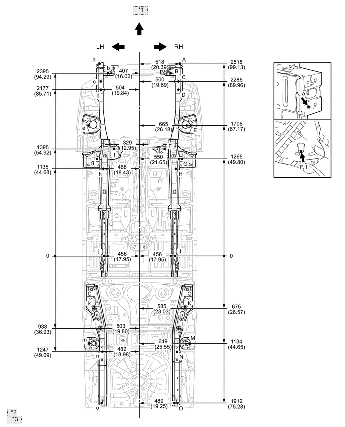
| *1 | Front |
| *2 | mm |
| *3 | (in.) |