REAR FLOOR SIDE MEMBER CUT AND JOIN REPLACEMENT SECTIONS
-
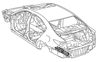
With the body lower back panel removed.
-
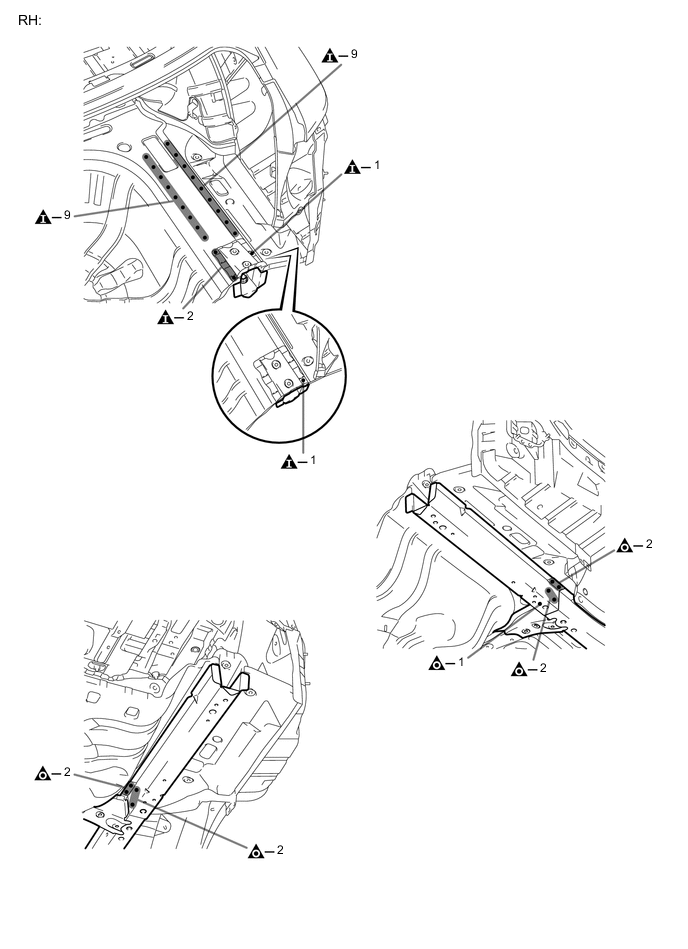
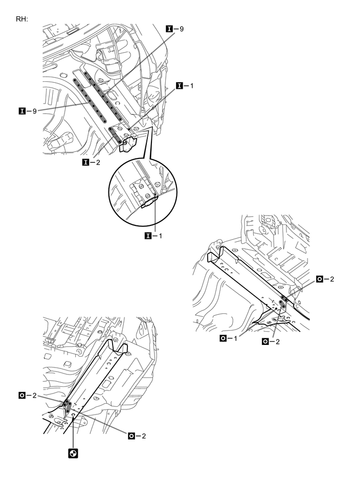
REMOVAL
Symbol meaning 
Remove Weld Points 
Remove Weld Points 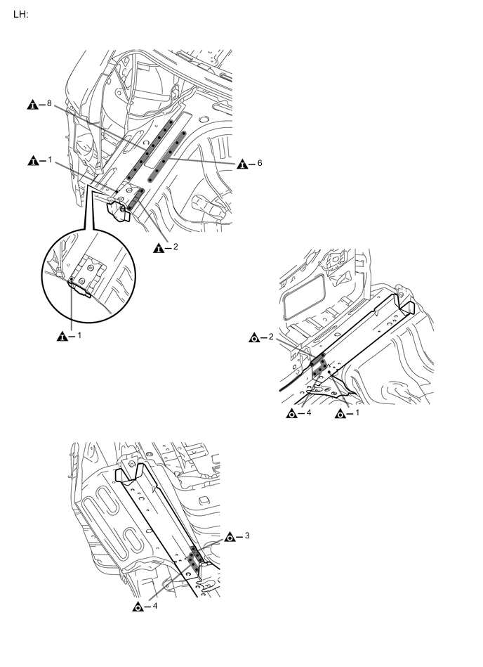
-
INSTALLATION
Symbol meaning Remove Weld Points 
Plug Weld 
Plug Weld 
Assembly Mark
-
For positioning of the new parts, align the installation standard holes of the rear floor side rear member and the member.
-
Temporarily install the new parts and measure each part of the new parts in accordance with the body dimension diagram. (See the body dimension diagram)
-
If the entire supply part is not needed, remove the part of the supply part that is needed.
-
After welding, apply undercoating to the corresponding parts. (See the painting / coating)
-
After applying the top coat, apply anti-rust agent to the internal panel portion of the closed section structural weld points.
INSTALLATION POINT
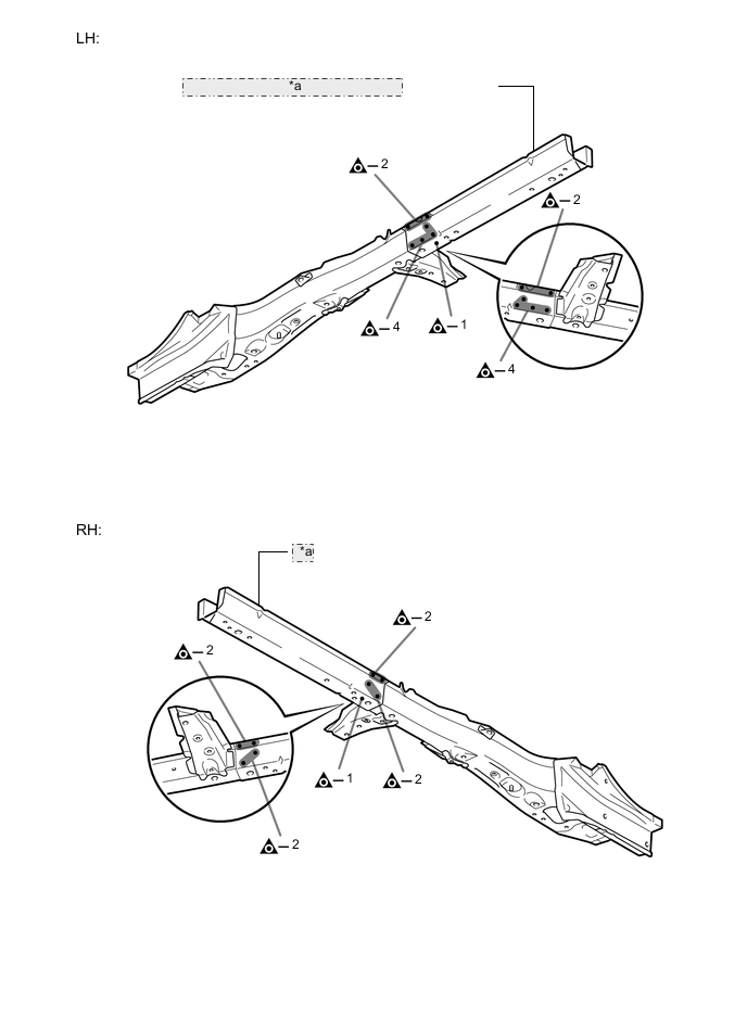
*a REAR FLOOR SIDE MEMBER SUB-ASSEMBLY 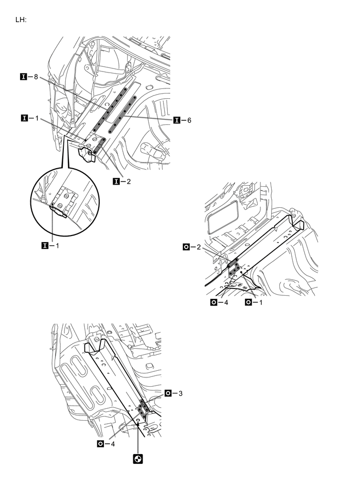
-