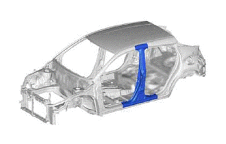
CENTER BODY PILLAR(for TMC Made) CUT AND JOIN REPLACEMENT SECTIONS
Info Added 2017-08-29 ![]()
-
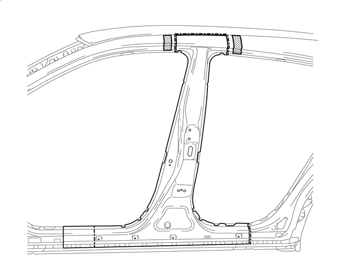
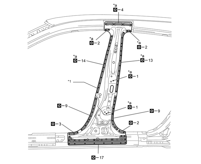
REMOVAL
Symbol Meaning 
Remove Weld Points 
Remove Weld Points 
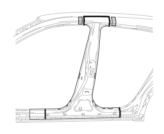
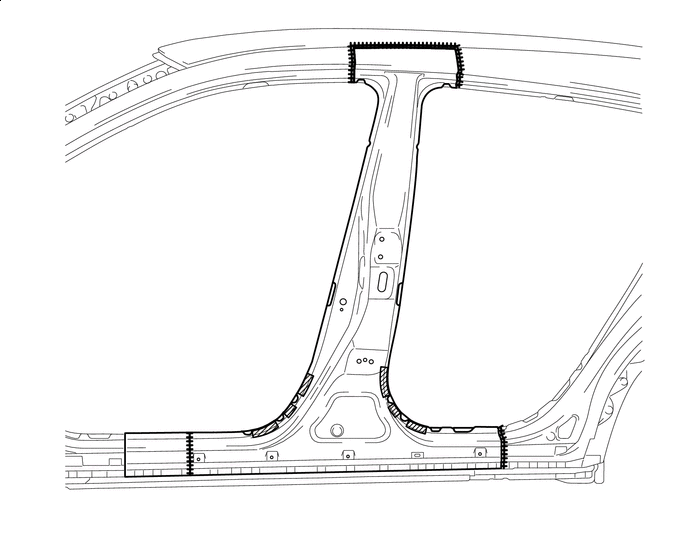
Cut with Disc Sander etc. 
Cut and Join Location 
Cut Location for Supply Parts
-
Do not butt weld or heat repair because the heat decreases the strength of areas where ultra high strength steel is used. (See the introduction)
-
Be careful when cutting as foamed sealing material is located near the cutting position.

Foamed Sealing Material - - 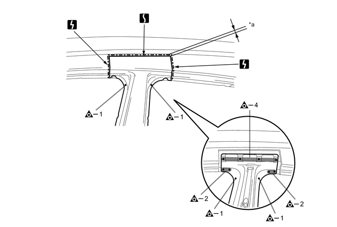
*a 20 mm (0.79 in.) - - 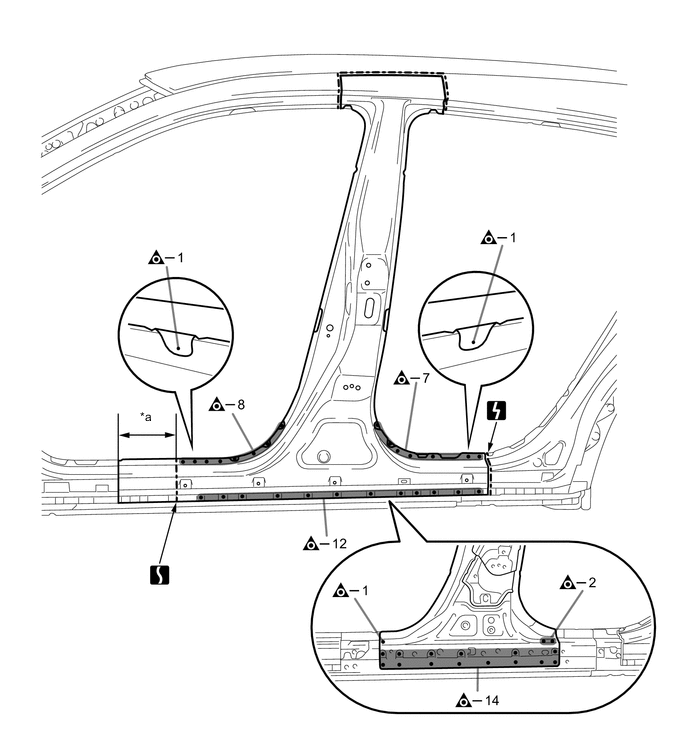
*a 175 mm (6.89 in.) - - 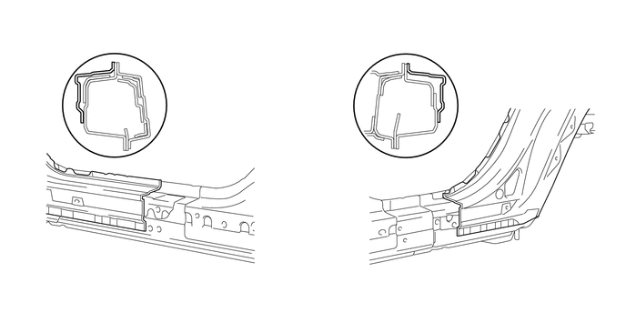
*a 20 mm (0.79 in.) - - -
When replace only the outer panel, please cut off a necessary range depending on a damage range.
-
Carefully cut the outer panel so not to damage the reinforcement.
-
Make sure that butt welding does not heat-affect the reinforcement when welding the outer panel.
-
-
-
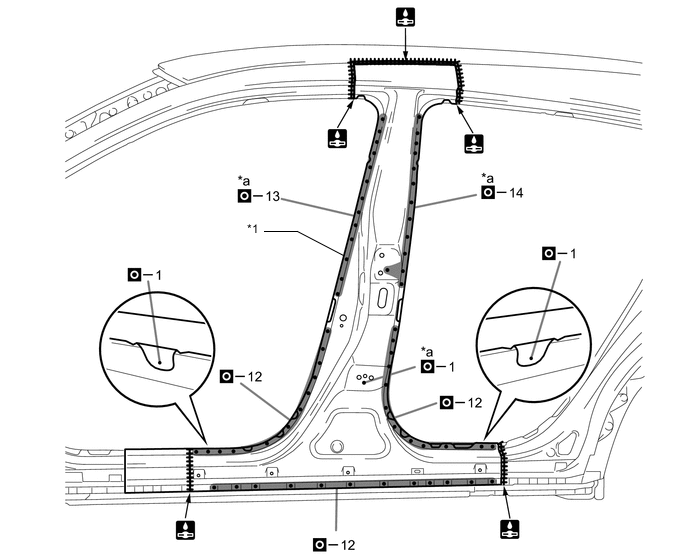
INSTALLATION
Symbol Meaning 
Plug Weld 
Plug Weld 
Fillet Weld 
Butt Weld
-
Inspect the fitting of the related parts around the new parts before welding. This affects the appearance of the finish.
-
Temporarily install the new parts and measure each part of the new parts in accordance with the body dimension diagram. (See the body dimensions)
-
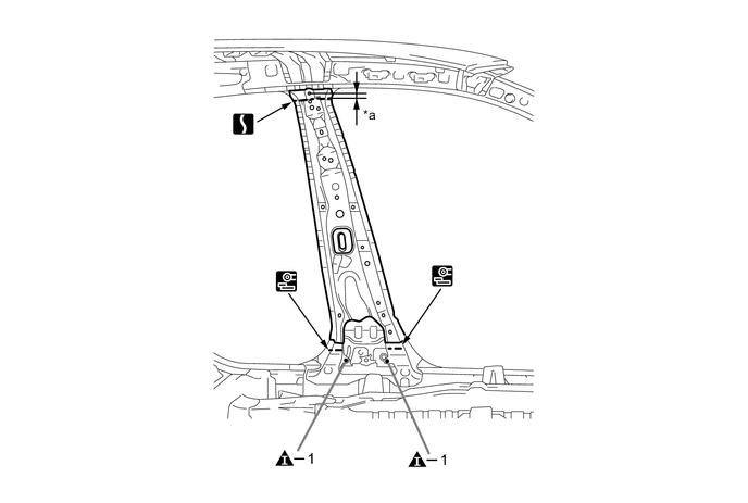
Weld the center body pillar reinforce sub-assembly lower to the vehicle side.
*1 CENTER BODY PILLAR REINFORCE SUB-ASSEMBLY LOWER - - *a 12 mm (0.47 in.) *b 15 mm (0.59 in.) -
Apply adhesive (3MTMAutomixTMPanel Bonding Adhesive #8115).
Tech Tips
-
Apply a light coat of adhesive around the plug welding points.
-
Apply enough adhesive to the panels.

Adhesive - - -
-
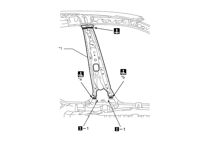
Weld the center body pillar reinforcement sub-assembly to the vehicle side.
*1 CENTER BODY PILLAR REINFORCEMENT SUB-ASSEMBLY - - *a Ultra High Strength Steel Welding Point - -
-
When welding 2 panels together including 1500 MPa ultra high strength steel.
*a: Plug weld Plug diameter 10 mm (0.39 in.) Wire type AWS A5.18 ER70S-3 Shield gas Metal active gas Note
Be sure to use Metal active gas (Ar 80% + CO220%) as the shield gas when plug welding.Sufficient weld strength cannot be assured when using 100% CO2shield gas.
Follow the welding conditions below when welding ultra high strength steel to assure sufficient weld strength. (When repairing this model)
-
-
Be careful when welding as foamed sealing material is located near the area that is cut and joined together.
Foamed Sealing Material - - -
Apply adhesive (3MTMAutomixTMPanel Bonding Adhesive #8115).
Tech Tips
-
Apply a light coat of adhesive around the plug welding points.
-
Apply enough adhesive to the panels.
Adhesive - - -
-
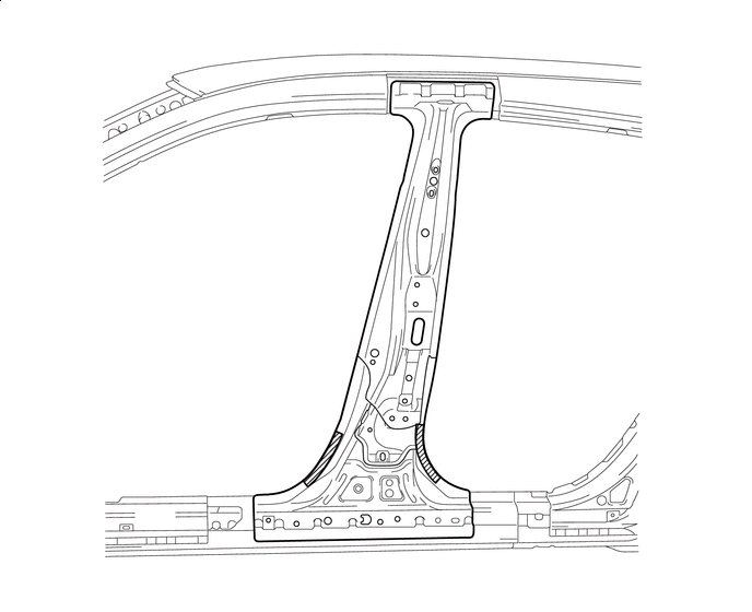
Weld the center body pillar outer to the vehicle side.
*1 CENTER BODY PILLAR OUTER - - *a Ultra High Strength Steel Welding Point - -
-
When welding more than 3 panels together including 1500 MPa ultra high strength steel. (When plug welding a third panel to 2 panels which are welded under the conditions described above.)
*a: Plug weld Plug diameter Same as the standard method (See the introduction) Wire type AWS A5.18 ER70S-3 Shield gas Metal active gas Note
Be sure to use Metal active gas (Ar 80% + CO220%) as the shield gas when plug welding.Sufficient weld strength cannot be assured when using 100% CO2shield gas.
Follow the welding conditions below when welding ultra high strength steel to assure sufficient weld strength. (When repairing this model)
-
-
After welding, apply the foamed sealing material to the corresponding parts. (See the painting/coating)
-
After welding, apply body sealer to the corresponding parts. (See the painting/coating)
-
After applying the top coat, apply anti-rust agent to the internal panel portion of the closed section structural weld points.
-