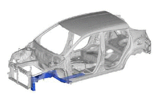
FRONT SIDE MEMBER(for TMMT Made) ASSEMBLY REPLACEMENT
Info Added 2017-08-29 ![]()
-
With the front fender apron assembly removed.
-
REMOVAL
Symbol Meaning 
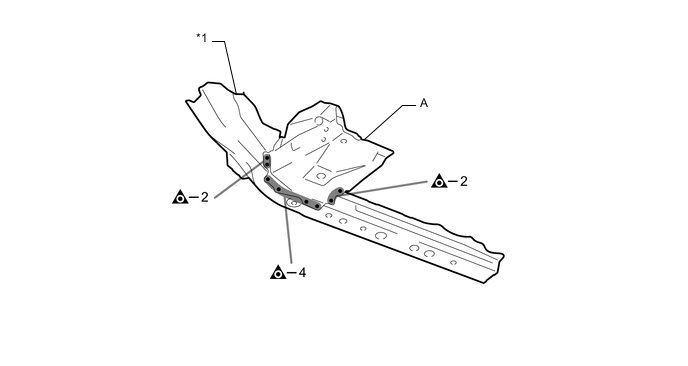
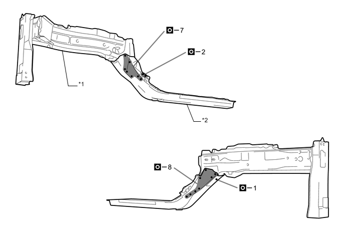
Remove Weld Points 
Cut with Disc Sander etc.
-
After removing the A, remove the front side member sub-assembly and the rear side member sub-assembly.
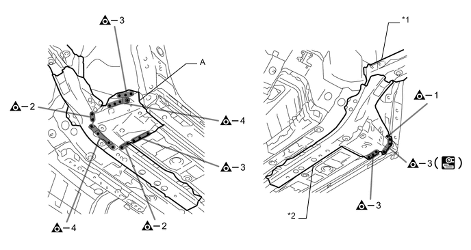
*1 FRONT SIDE MEMBER SUB-ASSEMBLY *2 REAR SIDE MEMBER SUB-ASSEMBLY 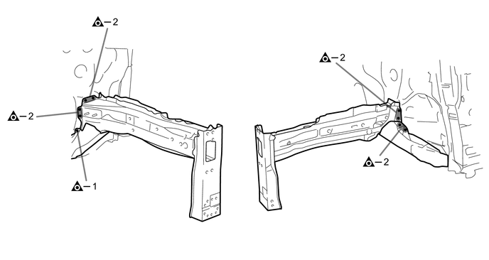
-
-
INSTALLATION
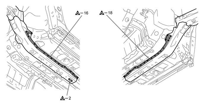
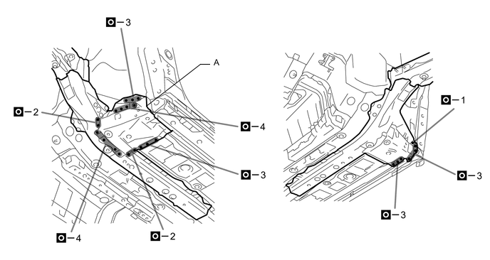
Symbol Meaning Remove Weld Points 
Plug Weld
-
Temporarily install the new parts and measure each part of the new parts in accordance with the body dimension diagram. (See the body dimensions)
-
Make sure to attach correctly in accordance with the body dimension diagram as this part affects the front wheel alignment.
-
Remove A from the new parts.
*1 REAR SIDE MEMBER SUB-ASSEMBLY - - -
Before temporarily installing the new parts, weld the front side member sub-assembly and the rear side member sub-assembly with the standard number of welding points.
*1 FRONT SIDE MEMBER SUB-ASSEMBLY *2 REAR SIDE MEMBER SUB-ASSEMBLY 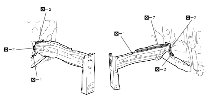

-
Weld the A to the vehicle side.
-
After welding, apply body sealer and undercoating to the corresponding parts. (See the painting/coating)
-
After applying the top coat, apply anti-rust agent to the internal panel portion of the closed section structural weld points.
-