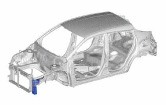
FRONT SIDE MEMBER(for TMC Made) CUT AND JOIN REPLACEMENT SECTIONS (SMALL AREAS)
Info Added 2017-08-29 ![]()
-
With the front side member extension assembly removed.
-
REMOVAL
Symbol Meaning 
Remove Weld Points 
Cut and Join Location
-
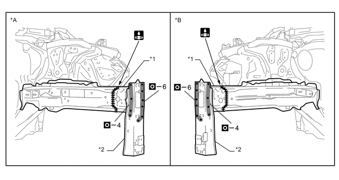
Carefully cut the front side member inner so as not to damage A.
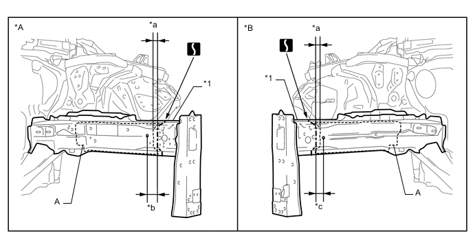
*A LH *B RH *1 FRONT SIDE MEMBER INNER - - *a 5 mm (0.20 in.) *b 35 mm (1.38 in.) *c 20 mm (0.79 in.) - - 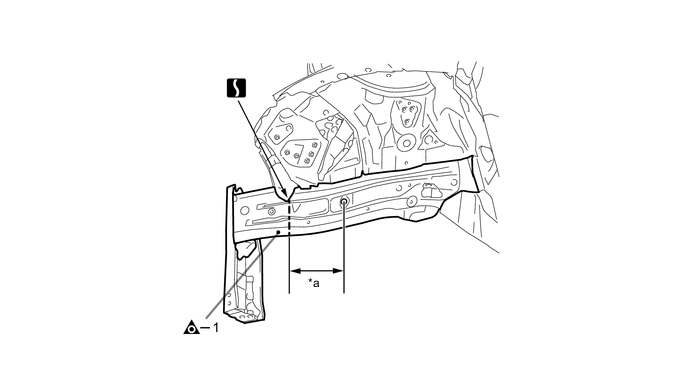
*a 180 mm (7.09 in.) - -
-
-
INSTALLATION
Symbol Meaning 
Plug Weld 
Butt Weld
-
Remove A from the new parts.
*1 FRONT SIDE MEMBER SUB-ASSEMBLY OUTER - - -
Temporarily install the new parts and measure each part of the new parts in accordance with the body dimension diagram. (See the body dimensions)
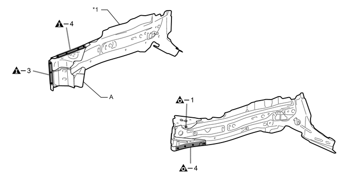
*A LH *B RH *1 FRONT SIDE MEMBER INNER *2 FRONT BUMPER MOUNTING REINFORCE SUB-ASSEMBLY 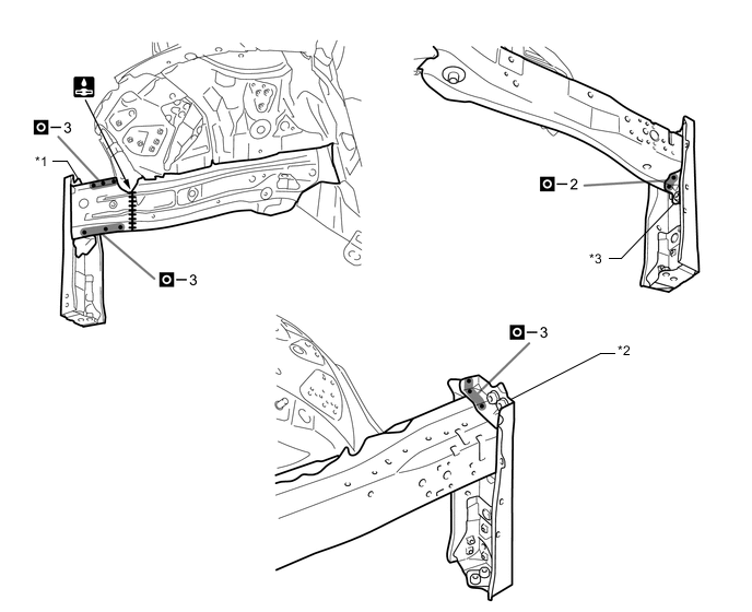
*1 FRONT SIDE MEMBER PLATE OUTER *2 FRONT SIDE MEMBER SUPPORT *3 FRONT SIDE MEMBER REINFORCEMENT FRONT - - -
After applying the top coat, apply anti-rust agent to the internal panel portion of the closed section structural weld points.
-