FIT STANDARD / ADJUSTMENT METHOD ADJUSTMENT
-
INSPECT HOOD SUB-ASSEMBLY
-
Check that the clearance measurements of areas "A" to "H" are within the standard ranges.
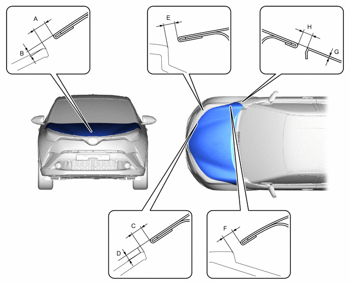
Standard Clearance Area Measurement Area Measurement A 2.8 to 5.8 mm (0.110 to 0.228 in.) B 0.5 to 3.5 mm (0.020 to 0.138 in.) C 2.8 to 5.8 mm (0.110 to 0.228 in.) D 0.5 to 3.5 mm (0.020 to 0.138 in.) E 1.8 to 5.8 mm (0.071 to 0.228 in.) F 1.8 to 5.8 mm (0.071 to 0.228 in.) G -1.5 to 1.5 mm (-0.059 to 0.059 in.) H 3.4 to 6.4 mm (0.134 to 0.252 in.)
Tech Tips
-
Centering bolts are used to install the hood hinges and hood lock. The hood and hood lock cannot be adjusted with the centering bolts installed. Substitute the centering bolts with standard bolts with washers when making adjustments.
-
The specified torque for standard bolts is shown in the standard bolt chart.
-
-
ADJUST HOOD SUB-ASSEMBLY
-
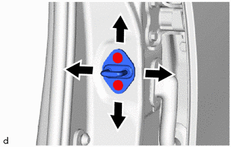
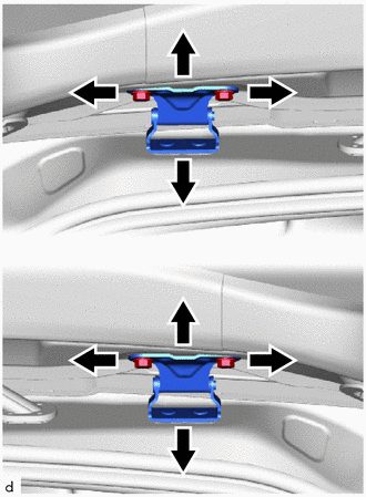
Horizontally and vertically adjust the hood.
-
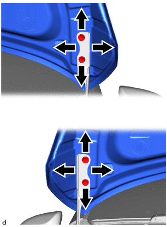
Loosen the 4 hinge bolts of the hood.
-
Adjust the clearance between the hood and front fenders by moving the hood.
-
Tighten the 4 hinge bolts after adjustment.
- Torque:
- 13 N*m { 133 kgf*cm, 10 ft.*lbf }
-
-
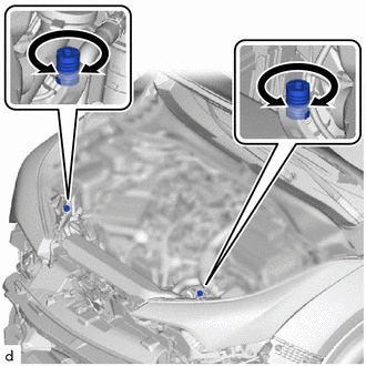
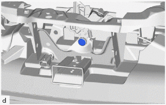
Adjust the height of the front end of the hood using the hood bumper cushions.
-
Adjust the 2 hood bumper cushions so that the heights of the hood and fenders are aligned.
Tech Tips
Raise or lower the front end of the hood by turning the 2 hood bumper cushions.
-
-
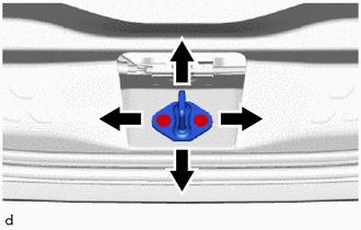
Adjust the hood lock.
-
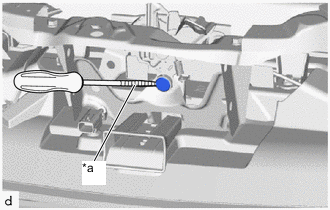
*a Protective Tape Using a screwdriver with its tip wrapped in protective tape, remove the hood lock nut cap.
-
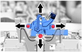
*1 Hood Lock Bolt Loosen the 2 bolts and hood lock bolt.
-
Adjust the hood lock assembly and tighten the 2 bolts and hood lock bolt.
- Torque:
- 7.5 N*m { 76 kgf*cm, 66 in.*lbf }
-
Check that the striker can engage the hood lock assembly smoothly.
-
Install a new hood lock nut cap.
-
-
-
ADJUST FRONT DOOR PANEL SUB-ASSEMBLY
-
Check that the clearance measurements of areas "A" to "Y" are within the standard ranges.
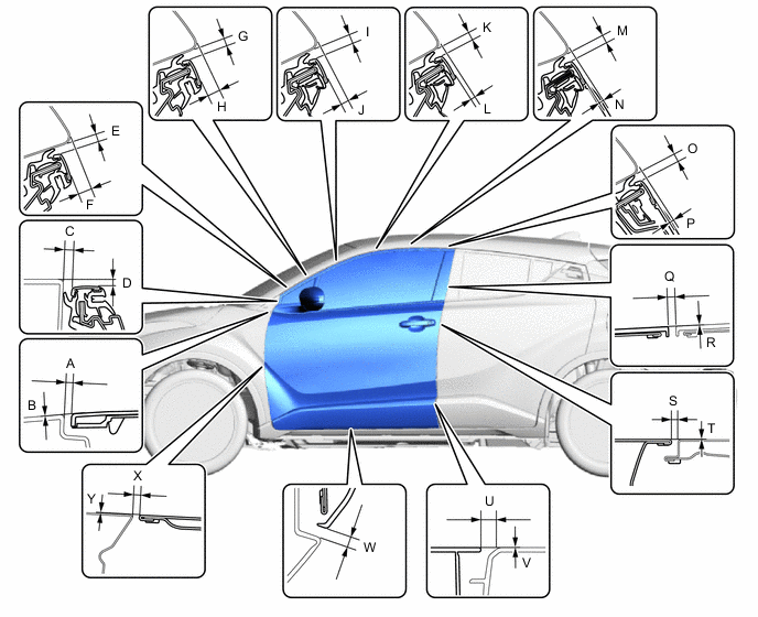
Standard Clearance Area Measurement Area Measurement A 2.1 to 6.1 mm (0.083 to 0.240 in.) B -2.0 to 2.0 mm (-0.079 to 0.079 in.) C 3.1 to 7.1 mm (0.122 to 0.280 in.) D 2.9 to 6.9 mm (0.114 to 0.272 in.) E 3.3 to 6.7 mm (0.130 to 0.264 in.) F 7.1 to 11.1 mm (0.280 to 0.437 in.) G 3.3 to 6.7 mm (0.130 to 0.264 in.) H 5.9 to 9.9 mm (0.232 to 0.390 in.) I 3.3 to 6.7 mm (0.130 to 0.264 in.) J 3.7 to 7.7 mm (0.146 to 0.303 in.) K 3.3 to 6.7 mm (0.130 to 0.264 in.) L 1.4 to 5.4 mm (0.055 to 0.213 in.) M 3.3 to 6.7 mm (0.130 to 0.264 in.) N 1.2 to 5.2 mm (0.047 to 0.205 in.) O 3.3 to 6.7 mm (0.130 to 0.264 in.) P 0.8 to 3.8 mm (0.031 to 0.150 in.) Q 2.4 to 6.4 mm (0.094 to 0.252 in.) R -2.0 to 2.0 mm (-0.079 to 0.079 in.) S 2.9 to 5.3 mm (0.114 to 0.209 in.) T -1.2 to 1.2 mm (-0.047 to 0.047 in.) U 7.5 to 11.5 mm (0.295 to 0.453 in.) V -2.0 to 2.0 mm (-0.079 to 0.079 in.) W 3.5 to 8.5 mm (0.138 to 0.335 in.) X 2.7 to 5.7 mm (0.106 to 0.224 in.) Y -1.5 to 1.5 mm (-0.059 to 0.059 in.) - -
Tech Tips
-
Use the same procedure for the RH side and LH side.
-
The following procedure is for the LH side.
-
Centering bolts are used to install the door hinges to the vehicle body and door. The door cannot be adjusted with the centering bolts installed. Substitute the centering bolts with standard bolts when making adjustments.
-
The specified torque for standard bolts is shown in the standard bolt chart.
-
-
INSPECT FRONT DOOR PANEL SUB-ASSEMBLY
-
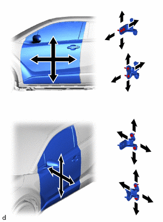
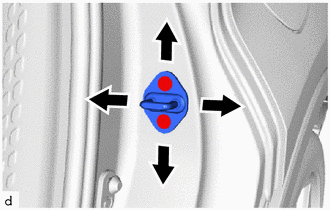
Using SST, loosen the 4 hinge bolts on the vehicle body and adjust the door position.
- SST
- 09812-00020
-
Tighten the 4 hinge bolts on the vehicle body after adjustment.
- Torque:
- 26 N*m { 265 kgf*cm, 19 ft.*lbf }
-
Loosen the 4 hinge bolts on the door and adjust the door position.
-
Tighten the 4 hinge bolts on the door after adjustment.
- Torque:
- 26 N*m { 265 kgf*cm, 19 ft.*lbf }
-
Using a T40 "TORX" socket wrench, slightly loosen the 2 striker mounting screws.
-
Using a brass bar and a hammer, hit the striker to adjust its position.
-
Using a T40 "TORX" socket wrench, tighten the 2 striker mounting screws after adjustment.
- Torque:
- 23 N*m { 235 kgf*cm, 17 ft.*lbf }
-
-
ADJUST REAR DOOR PANEL SUB-ASSEMBLY
-
Check that the clearance measurements of areas "A" to "W" are within the standard ranges.
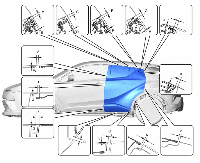
Standard Clearance Area Measurement Area Measurement A 3.3 to 6.7 mm (0.130 to 0.264 in.) B 0.9 to 4.9 mm (0.035 to 0.193 in.) C 3.3 to 6.7 mm (0.130 to 0.264 in.) D 1.8 to 5.8 mm (0.071 to 0.228 in.) E 3.3 to 6.7 mm (0.130 to 0.264 in.) F 2.5 to 6.5 mm (0.098 to 0.256 in.) G 3.3 to 6.7 mm (0.130 to 0.264 in.) H 2.3 mm (0.091 in.) I 3.3 to 7.3 mm (0.130 to 0.287 in.) J 1.0 mm (0.039 in.) K 2.6 to 6.6 mm (0.102 to 0.260 in.) L 0.7 mm (0.028 in.) M 2.6 to 5.6 mm (0.102 to 0.220 in.) N 2.1 to 6.1 mm (0.083 to 0.240 in.) O 3.3 to 8.3 mm (0.130 to 0.327 in.) P -2.5 to 2.5 mm (-0.098 to 0.098 in.) Q 3.5 to 8.5 mm (0.138 to 0.335 in.) R 7.5 to 11.5 mm (0.295 to 0.453 in.) S -2.0 to 2.0 mm (-0.079 to 0.079 in.) T 2.9 to 5.3 mm (0.114 to 0.209 in.) U -1.2 to 1.2 mm (-0.047 to 0.047 in.) V 2.4 to 6.4 mm (0.094 to 0.252 in.) W -2.0 to 2.0 mm (-0.079 to 0.079 in.) - -
Tech Tips
-
Use the same procedure for the RH side and LH side.
-
The following procedure is for the LH side.
-
Centering bolts are used to install the door hinges to the vehicle body and door. The door cannot be adjusted with the centering bolts installed. Substitute the centering bolts with standard bolts when making adjustments.
-
The specified torque for standard bolts is shown in the standard bolt chart.
-
-
ADJUST REAR DOOR PANEL SUB-ASSEMBLY
-
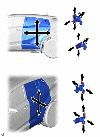
Using SST, loosen the 4 hinge bolts on the vehicle body and adjust the door position.
- SST
- 09812-00020
-
Tighten the 4 hinge bolts on the vehicle body after adjustment.
- Torque:
- 26 N*m { 265 kgf*cm, 19 ft.*lbf }
-
Loosen the 4 hinge bolts on the door and adjust the door position.
-
Tighten the 4 hinge bolts on the door after adjustment.
- Torque:
- 26 N*m { 265 kgf*cm, 19 ft.*lbf }
-
Using a T40 "TORX" socket wrench, slightly loosen the 2 striker mounting screws.
-
Using a brass bar and a hammer, hit the striker to adjust its position.
-
Using a T40 "TORX" socket wrench, tighten the 2 striker mounting screws after adjustment.
- Torque:
- 23 N*m { 235 kgf*cm, 17 ft.*lbf }
-
-
INSPECT BACK DOOR
-
Check that the clearance measurements of areas "A" to "O" are within the standard ranges.
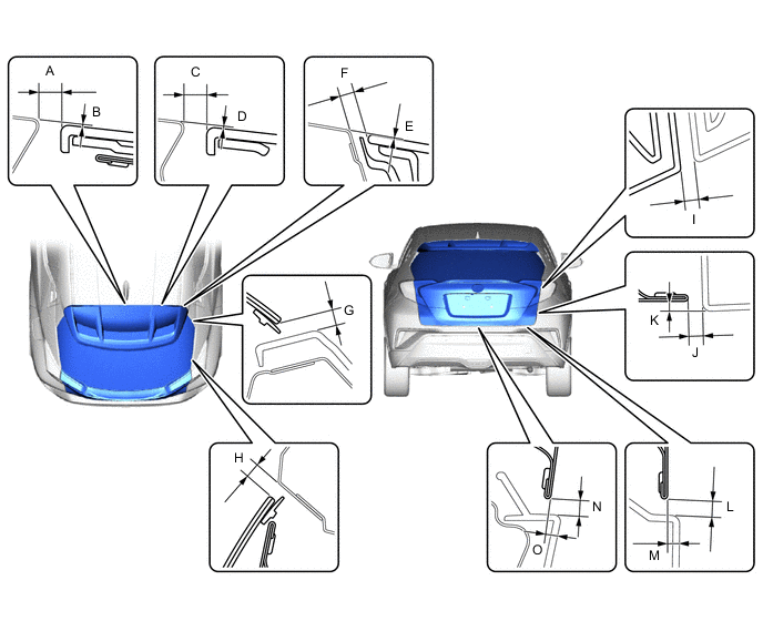
Standard Clearance Area Measurement Area Measurement A 7.1 to 11.1 mm (0.280 to 0.437 in.) B -1.0 to 3.0 mm (-0.039 to 0.118 in.) C 7.1 to 11.1 mm (0.280 to 0.437 in.) D -1.0 to 3.0 mm (-0.039 to 0.118 in.) E -2.0 to 2.0 mm (-0.079 to 0.079 in.) F 4.0 to 8.0 mm (0.157 to 0.315 in.) G 3.5 to 8.5 mm (0.138 to 0.335 in.) H 3.5 to 8.5 mm (0.138 to 0.335 in.) I 3.3 to 7.3 mm (0.130 to 0.287 in.) J 3.5 to 7.5 mm (0.138 to 0.295 in.) K 2.4 to 5.4 mm (0.094 to 0.213 in.) L 4.0 to 8.0 mm (0.157 to 0.315 in.) M 2.8 to 5.8 mm (0.110 to 0.228 in.) N 4.0 to 8.0 mm (0.157 to 0.315 in.) O 3.8 to 6.8 mm (0.150 to 0.268 in.) - -
Tech Tips
-
Centering bolts are used to install the door hinges to the door. The door cannot be adjusted with the centering bolts installed. Substitute the centering bolts with standard bolts (with washers) when making adjustments.
-
The specified torque for standard bolts is shown in the standard bolt chart.
-
-
ADJUST BACK DOOR
-
Loosen the 4 hinge bolts on the back door and adjust the back door position.
-
Tighten the 4 hinge bolts on the back door after adjustment.
- Torque:
- 19 N*m { 194 kgf*cm, 14 ft.*lbf }
-
Using a T40 "TORX" socket wrench, slightly loosen the 2 striker mounting screws.
-
Using a brass bar and a hammer, hit the striker to adjust its position.
-
Using a T40 "TORX" socket wrench, tighten the 2 striker mounting screws after adjustment.
- Torque:
- 23 N*m { 235 kgf*cm, 17 ft.*lbf }
-