ENGINE COMPARTMENT THREE-DIMENSIONAL DISTANCE
Tech Tips
-
In cases in which only one dimension is given, left and right are symmetrical.
-
For symbols, capital letters indicate right side of vehicle, small letters indicate left side of vehicle (seen from rear).
| Symbol | Name | Hole Diameter mm (in.) |
|---|---|---|
| A, a | Front Fender Installation Nut | M6 (0.24) |
| B, b | Front Spring Support Standard Hole | φ11 (0.43) |
| C, c | Hood Hinge Installation Nut | M8 (0.31) |
| D | Cowl Top Inner Panel Center Mark | - |
| E, e | Front Side Member Standard Hole | φ15 (0.59) |
| F, f | Front Side Member Standard Hole | φ10 (0.39) |
| G, g | Radiator Seal Installation Hole | φ8 (0.31) |
| H, h | Front Bumper Reinforcement Installation Nut | M10 (0.39) |
| j | Radiator Support Brace Installation Nut | M6 (0.24) |
| K, k | Front Fender Mounting Bracket Standard Hole | φ10 (0.39) |
| L, l | Hood Cushion Installation Hole | φ15 (0.59) |
| M, m | Headlight Installation Hole | 9X9 (0.35X0.35) |
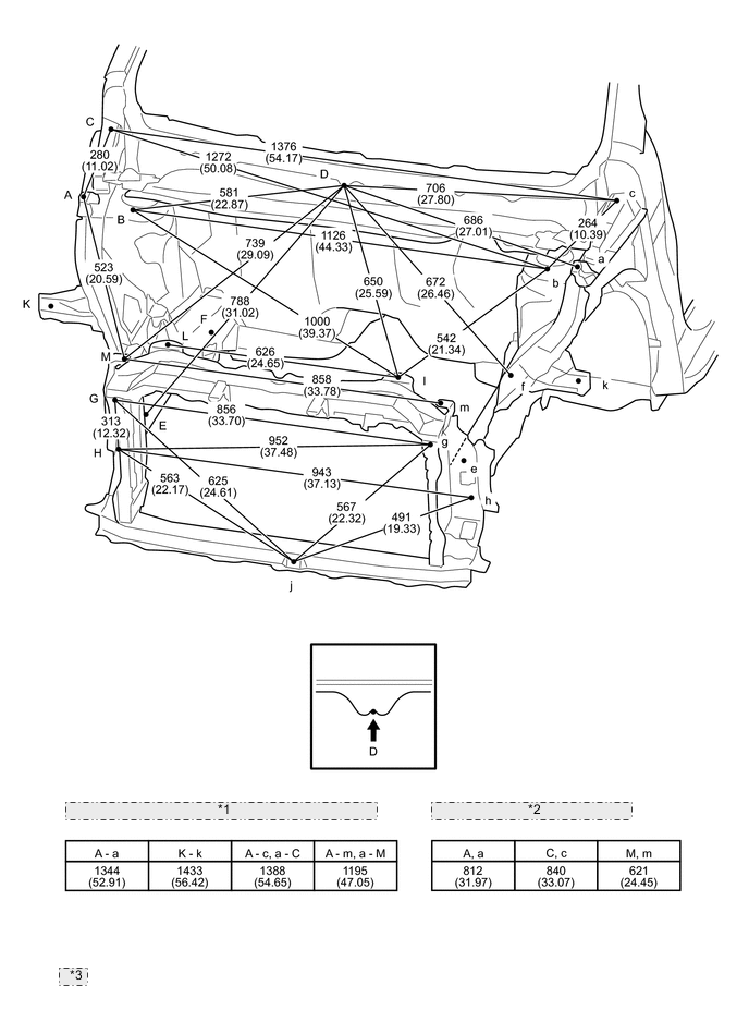
| *1 | Distance between points other than those above |
| *2 | Height from Imaginary Datum Line |
| *3 | mm (in.) |