WHEN REMOVING,INSTALLING,REPAIRING OR REPLACING PARTS WHEEL ALIGNMENT STANDARD
Note
For vehicles equipped with VSC, if wheel alignment has been adjusted, and if suspension or underbody components have been removed/installed or replaced, be sure to perform the following initialization procedure in order for the system to function normally:
-
Check that the steering wheel is in the centered position.
-
Disconnect the negative battery terminal for more than 2 seconds.
-
Reconnect the negative battery terminal.
-
Perform zero point calibration of the yaw rate and deceleration sensor and test mode inspection.
-
FRONT WHEEL ALIGNMENT
-
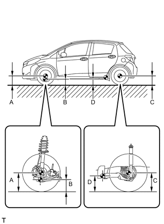
MEASURE VEHICLE HEIGHT (for TMC Made)
Vehicle Height (Unloaded Vehicle) Model Tire Size Engine Front A-B Rear C-D Except for Rough Road Package 175/70 R14 1KR-FE 95 mm
(3.74 in.)
32 mm
(1.26 in.)
175/65 R15 1KR-FE 95 mm
(3.74 in.)
32 mm
(1.26 in.)
1NR-FE 95 mm
(3.74 in.)
33 mm
(1.30 in.)
175/65 R14 1KR-FE 87 mm
(3.43 in.)
24 mm
(0.94 in.)
185/60 R15 1KR-FE 87 mm
(3.43 in.)
24 mm
(0.94 in.)
1NR-FE 87 mm
(3.43 in.)
24 mm
(0.94 in.)
Rough Road Package 175/65 R14 1KR-FE 67 mm
(2.64 in.)
4 mm
(0.16 in.)
185/60 R15 1KR-FE 67 mm
(2.64 in.)
4 mm
(0.16 in.)
1NR-FE 67 mm
(2.64 in.)
4 mm
(0.16 in.)
Note
-
Before inspecting the wheel alignment, check the vehicle height.
-
The standard value shown here is a value that is used for adjusting the wheel alignment and does not indicate the height of an actual vehicle.
Tech Tips
Bounce the vehicle up and down at the corners to stabilize the suspension before inspecting the vehicle height.
-
-
MEASURE VEHICLE HEIGHT (for TMMF Made)
Vehicle Height (Unloaded Vehicle) Model Tire Size Engine Front A-B Rear C-D Except for Rough Road Package 175/70 R14 1KR-FE 95 mm
(3.74 in.)
32 mm
(1.26 in.)
1NR-FE 95 mm
(3.74 in.)
33 mm
(1.30 in.)
1ND-TV 97 mm
(3.82 in.)
33 mm
(1.30 in.)
175/65 R15 1KR-FE 95 mm
(3.74 in.)
32 mm
(1.26 in.)
195/50 R16 1NR-FE 100 mm
(3.94 in.)
33 mm
(1.30 in.)
1ND-TV 100 mm
(3.94 in.)
33 mm
(1.30 in.)
Except for Rough Road Package
w/ Rear Seat
175/65 R14 1KR-FE 87 mm
(3.43 in.)
24 mm
(0.94 in.)
Except for Rough Road Package
w/o Rear Seat
87 mm
(3.43 in.)
21 mm
(0.83 in.)
Except for Rough Road Package
w/ Rear Seat
185/60 R15 1KR-FE 87 mm
(3.43 in.)
24 mm
(0.94 in.)
1NR-FE 87 mm
(3.43 in.)
24 mm
(0.94 in.)
1ND-TV 89 mm
(3.50 in.)
25 mm
(0.98 in.)
Except for Rough Road Package
w/o Rear Seat
1KR-FE 87 mm
(3.43 in.)
21 mm
(0.83 in.)
1NR-FE 87 mm
(3.43 in.)
21 mm
(0.83 in.)
1ND-TV 89 mm
(3.50 in.)
21 mm
(0.83 in.)
Except for Rough Road Package
w/o Panorama Roof
175/65 R15 1NR-FE 95 mm
(3.74 in.)
33 mm
(1.30 in.)
1ND-TV 97 mm
(3.82 in.)
33 mm
(1.30 in.)
Except for Rough Road Package
w/ Panorama Roof
1NR-FE 100 mm
(3.94 in.)
33 mm
(1.30 in.)
1ND-TV 100 mm
(3.94 in.)
33 mm
(1.30 in.)
Rough Road Package 175/65 R14 1KR-FE 67 mm
(2.64 in.)
4 mm
(0.16 in.)
185/60 R15 1KR-FE 67 mm
(2.64 in.)
4 mm
(0.16 in.)
1NR-FE 67 mm
(2.64 in.)
4 mm
(0.16 in.)
1ND-TV 69 mm
(2.72 in.)
5 mm
(0.20 in.)
Note
-
Before inspecting the wheel alignment, check the vehicle height.
-
The standard value shown here is a value that is used for adjusting the wheel alignment and does not indicate the height of an actual vehicle.
Tech Tips
Bounce the vehicle up and down at the corners to stabilize the suspension before inspecting the vehicle height.
-
-
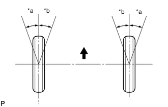
Text in Illustration *a Inside *b Outside 
Front of the Vehicle INSPECT WHEEL TURNING ANGLE (for TMC Made)
-
Fully turn the steering wheel left and right, and measure the wheel turning angle.
Wheel Turning Angle (Unloaded Vehicle) Model Tire Size Engine Inside Wheel Outside Wheel Except for Rough Road Package 175/70 R14 1KR-FE 40°46 ' +/- 2°
(40.77° +/- 2°)
35°05'
(35.08°)
175/65 R15 1KR-FE 40°46 ' +/- 2°
(40.77° +/- 2°)
35°05'
(35.08°)
1NR-FE 40°46' +/- 2°
(40.77° +/- 2°)
35°05'
(35.08°)
175/65 R14 1KR-FE 41°01' +/- 2°
(41.02° +/- 2°)
35°15'
(35.25°)
185/60 R15 1KR-FE 41°01' +/- 2°
(41.02° +/- 2°)
35°15'
(35.25°)
1NR-FE 41°01' +/- 2°
(41.02° +/- 2°)
35°15'
(35.25°)
Rough Road Package 175/65 R14 1KR-FE 41°35' +/- 2°
(41.58° +/- 2°)
35°43'
(35.72°)
185/60 R15 1KR-FE 41°35' +/- 2°
(41.58° +/- 2°)
35°43'
(35.72°)
1NR-FE 41°35' +/- 2°
(41.58° +/- 2°)
35°43'
(35.72°)
If the right and left inside wheel angles are not within the specified range, check the right and left rack end lengths.
-
-
Text in Illustration *a Inside *b Outside Front of the Vehicle INSPECT WHEEL TURNING ANGLE (for TMMF Made)
-
Fully turn the steering wheel left and right, and measure the wheel turning angle.
Wheel Turning Angle (Unloaded Vehicle) Model Tire Size Engine Inside Wheel Outside Wheel Except for Rough Road Package 175/70 R14 1KR-FE 40°46' +/- 2°
(40.77° +/- 2°)
35°05'
(35.08°)
1NR-FE 40°46' +/- 2°
(40.77° +/- 2°)
35°05'
(35.08° )
1ND-TV 40°45' +/- 2°
(40.75° +/- 2°)
35°03'
(35.05°)
175/65 R15 1KR-FE 40°46' +/- 2°
(40.77° +/- 2°)
35°05'
(35.08°)
195/50 R16 1NR-FE 32°27' +/- 2°
(32.45° +/- 2°)
29°27'
(29.45°)
1ND-TV 32°27' +/- 2°
(32.45° +/- 2°)
29°27'
(29.45°)
Except for Rough Road Package
w/ Rear Seat
175/65 R14 1KR-FE 41°01' +/- 2°
(41.02° +/- 2°)
35°15'
(35.25°)
Except for Rough Road Package
w/o Rear Seat
41°01' +/- 2°
(41.02° +/- 2°)
35°15'
(35.25°)
Except for Rough Road Package
w/ Rear Seat
185/60 R15 1KR-FE 41°01' +/- 2°
(41.02° +/- 2°)
35°15'
(35.25°)
1NR-FE 41°01' +/- 2°
(41.02° +/- 2°)
35°15'
(35.25°)
1ND-TV 40°59' +/- 2°
(40.98° +/- 2°)
35°13'
(35.22°)
Except for Rough Road Package
w/o Rear Seat
1KR-FE 41°01' +/- 2°
(41.02° +/- 2°)
35°15'
(35.25°)
1NR-FE 41°01' +/- 2°
(41.02° +/- 2°)
35°15'
(35.25°)
1ND-TV 40°59' +/- 2°
(40.98° +/- 2°)
35°13'
(35.22°)
Except for Rough Road Package
w/o Panorama Roof
175/65 R15 1NR-FE 40°46' +/- 2°
(40.77° +/- 2°)
35°05'
(35.08°)
1ND-TV 40°45' +/- 2°
(40.75° +/- 2°)
35°03'
(35.05°)
Except for Rough Road Package
w/ Panorama Roof
1NR-FE 40°39' +/- 2°
(40.65° +/- 2°)
34°58'
(34.97°)
1ND-TV 40°39' +/- 2°
(40.65° +/- 2°)
34°58'
(34.97°)
Rough Road Package 175/65 R14 1KR-FE 41°35 +/- 2°
(41.58° +/- 2°)
35°43'
(35.72°)
185/60 R15 1KR-FE 41°35 +/- 2°
(41.58° +/- 2°)
35°43'
(35.72°)
1NR-FE 41°35' +/- 2°
(41.58° +/- 2°)
35°43'
(35.72°)
1ND-TV 41°33' +/- 2°
(41.55° +/- 2°)
35°41'
(35.68°)
If the right and left inside wheel angles are not within the specified range, check the right and left rack end lengths.
-
-
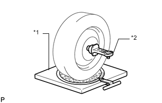
Text in Illustration *1 Alignment tester *2 Camber-caster-steering axis inclination gauge INSPECT CAMBER, CASTER AND STEERING AXIS INCLINATION (for TMC Made)
-
Put the front wheel on the center of the alignment tester.
-
Remove the wheel cap.
-
Set the camber-caster-steering axis inclination gauge at the center of the axle hub or drive shaft.
-
Inspect the camber, caster and steering axis inclination.
Camber Inclination (Unloaded Vehicle) Model Tire Size Engine Camber Except for Rough Road Package 175/70 R14 1KR-FE -0°20' +/- 45'
(-0.33° +/- 0.75°)
175/65 R15 1KR-FE -0°20' +/- 45'
(-0.33° +/- 0.75°)
1NR-FE -0°20' +/- 45'
(-0.33° +/- 0.75°)
175/65 R14 1KR-FE -0°15' +/- 45'
(-0.25° +/- 0.75°)
185/60 R15 1KR-FE -0°15' +/- 45'
(-0.25° +/- 0.75°)
1NR-FE -0°15' +/- 45'
(-0.25° +/- 0.75°)
Rough Road Package 175/65 R14 1KR-FE 0°02' +/- 45'
(0.03° +/- 0.75°)
185/60 R15 1KR-FE 0°02' +/- 45'
(0.03° +/- 0.75°)
1NR-FE 0°02' +/- 45'
(0.03° +/- 0.75°)
Caster Inclination (Unloaded Vehicle) Model Tire Size Engine Caster Except for Rough Road Package 175/70 R14 1KR-FE 5°03' +/- 45'
(5.05° +/- 0.75°)
175/65 R15 1KR-FE 5°03' +/- 45'
(5.05° +/- 0.75°)
1NR-FE 5°01' +/- 45'
(5.02° +/- 0.75°)
175/65 R14 1KR-FE 4°54' +/- 45'
(4.90° +/- 0.75°)
185/60 R15 1KR-FE 4°55' +/- 45'
(4.92° +/- 0.75°)
1NR-FE 4°54' +/- 45'
(4.90° +/- 0.75°)
Rough Road Package 175/65 R14 1KR-FE 4°35' +/- 45'
(4.58° +/- 0.75°)
185/60 R15 1KR-FE 4°35' +/- 45'
(4.58° +/- 0.75°)
1NR-FE 4°35' +/- 45'
(4.58° +/- 0.75°)
Steering Axis Inclination (Unloaded Vehicle) Model Tire Size Engine Steering Axis Inclination
(Reference)
Except for Rough Road Package 175/70 R14 1KR-FE 11°19'
(11.32°)
175/65 R15 1KR-FE 11°19'
(11.32°)
1NR-FE 11°19'
(11.32°)
175/65 R14 1KR-FE 11°09'
(11.15°)
185/60 R15 1KR-FE 11°09'
(11.15°)
1NR-FE 11°09'
(11.15°)
Rough Road Package 175/65 R14 1KR-FE 10°40'
(10.67°)
185/60 R15 1KR-FE 10°40'
(10.67°)
1NR-FE 10°40'
(10.67°)
Note
-
Perform the inspection while the vehicle is empty (without a spare tire or tools on board).
-
The tolerance for the difference between the left and right wheels is 30' (0.5°) or less for both the camber and caster.
-
-
Remove the camber-caster-steering axis inclination gauge and attachment.
-
Install the wheel cap.
If the caster and steering axis inclination are not within the specified values after the camber has been correctly adjusted, recheck the suspension parts for damage and wear.
-
-
Text in Illustration *1 Alignment tester *2 Camber-caster-steering axis inclination gauge INSPECT CAMBER, CASTER AND STEERING AXIS INCLINATION (for TMMF Made)
-
Put the front wheel on the center of the alignment tester.
-
Remove the wheel cap.
-
Set the camber-caster-steering axis inclination gauge at the center of the axle hub or drive shaft.
-
Inspect the camber, caster and steering axis inclination.
Camber Inclination (Unloaded Vehicle) Model Tire Size Engine Camber Except for Rough Road Package 175/70 R14 1KR-FE -0°20' +/- 45'
(-0.33° +/- 0.75°)
1NR-FE -0°20' +/- 45'
(-0.33° +/- 0.75°)
1ND-TV -0°21' +/- 45'
(-0.35° +/- 0.75°)
175/65 R15 1KR-FE -0°20' +/- 45'
(-0.33° +/- 0.75°)
195/50 R16 1NR-FE -0°23' +/- 45'
(-0.38° +/- 0.75°)
1ND-TV -0°23' +/- 45'
(-0.38° +/- 0.75°)
Except for Rough Road Package
w/ Rear Seat
175/65 R14 1KR-FE -0°15' +/- 45'
(-0.25° +/- 0.75°)
Except for Rough Road Package
w/o Rear Seat
-0°15' +/- 45'
(-0.25° +/- 0.75°)
Except for Rough Road Package
w/ Rear Seat
185/60 R15 1KR-FE -0°15' +/- 45'
(-0.25° +/- 0.75°)
1NR-FE -0°15' +/- 45'
(-0.25° +/- 0.75°)
1ND-TV -0°16' +/- 45'
(-0.27° +/- 0.75°)
Except for Rough Road Package
w/o Rear Seat
1KR-FE -0°15' +/- 45'
(-0.25° +/- 0.75°)
1NR-FE -0°15' +/- 45'
(-0.25° +/- 0.75°)
1ND-TV -0°16' +/- 45'
(-0.27° +/- 0.75°)
Except for Rough Road Package
w/o Panorama Roof
175/65 R15 1NR-FE -0°20' +/- 45'
(-0.33° +/- 0.75°)
1ND-TV -0°21' +/- 45'
(-0.35° +/- 0.75°)
Except for Rough Road Package
w/ Panorama Roof
1NR-FE -0°23' +/- 45'
(-0.38° +/- 0.75°)
1ND-TV -0°23' +/- 45'
(-0.38° +/- 0.75°)
Rough Road Package 175/65 R14 1KR-FE 0°02' +/- 45'
(0.03° +/- 0.75°)
185/60 R15 1KR-FE 0°02' +/- 45'
(0.03° +/- 0.75°)
1NR-FE 0°02' +/- 45'
(0.03° +/- 0.75°)
1ND-TV 0°01' +/- 45'
(0.02° +/- 0.75°)
Caster Inclination (Unloaded Vehicle) Model Tire Size Engine Caster Except for Rough Road Package 175/70 R14 1KR-FE 5°03' +/- 45'
(5.05° +/- 0.75°)
1NR-FE 5°01' +/- 45'
(5.02° +/- 0.75°)
1ND-TV 5°00' +/- 45'
(5.00° +/- 0.75°)
175/65 R15 1KR-FE 5°03' +/- 45'
(5.05° +/- 0.75°)
195/50 R16 1NR-FE 5°00' +/- 45'
(5.00° +/- 0.75°)
1ND-TV 4°59' +/- 45'
(4.98° +/- 0.75°)
Except for Rough Road Package
w/ Rear Seat
175/65 R14 1KR-FE 4°54' +/- 45'
(4.90° +/- 0.75°)
Except for Rough Road Package
w/o Rear Seat
4°48' +/- 45'
(4.80° +/- 0.75°)
Except for Rough Road Package
w/ Rear Seat
185/60 R15 1KR-FE 4°55' +/- 45'
(4.92° +/- 0.75°)
1NR-FE 4°54' +/- 45'
(4.90° +/- 0.75°)
1ND-TV 4°52' +/- 45'
(4.87° +/- 0.75°)
Except for Rough Road Package
w/o Rear Seat
1KR-FE 4°49' +/- 45'
(4.82° +/- 0.75°)
1NR-FE 4°48' +/- 45'
(4.80° +/- 0.75°)
1ND-TV 4°46' +/- 45'
(4.77° +/- 0.75°)
Except for Rough Road Package
w/o Panorama Roof
175/65 R15 1NR-FE 5°01' +/- 45'
(5.02° +/- 0.75°)
1ND-TV 5°00' +/- 45'
(5.00° +/- 0.75°)
Except for Rough Road Package
w/ Panorama Roof
1NR-FE 5°00' +/- 45'
(5.00° +/- 0.75°)
1ND-TV 4°59' +/- 45'
(4.98° +/- 0.75°)
Rough Road Package 175/65 R14 1KR-FE 4°35' +/- 45'
(4.58° +/- 0.75°)
185/60 R15 1KR-FE 4°35' +/- 45'
(4.58° +/- 0.75°)
1NR-FE 4°35' +/- 45'
(4.58° +/- 0.75°)
1ND-TV 4°32' +/- 45'
(4.53° +/- 0.75°)
Steering Axis Inclination (Unloaded Vehicle) Model Tire Size Engine Steering Axis Inclination
(Reference)
Except for Rough Road Package 175/70 R14 1KR-FE 11°19'
(11.32°)
1NR-FE 11°19'
(11.32°)
1ND-TV 11°21'
(11.35°)
175/65 R15 1KR-FE 11°19'
(11.32°)
195/50 R16 1NR-FE 11°25'
(11.42°)
1ND-TV 11°25'
(11.42°)
Except for Rough Road Package
w/ Rear Seat
175/65 R14 1KR-FE 11°09'
(11.15°)
Except for Rough Road Package
w/o Rear Seat
11°09'
(11.15°)
Except for Rough Road Package
w/ Rear Seat
185/60 R15 1KR-FE 11°09'
(11.15°)
1NR-FE 11°09'
(11.15°)
1ND-TV 11°11'
(11.18°)
Except for Rough Road Package
w/o Rear Seat
1KR-FE 11°09'
(11.15°)
1NR-FE 11°09'
(11.15°)
1ND-TV 11°11'
(11.18°)
Except for Rough Road Package
w/o Panorama Roof
175/65 R15 1NR-FE 11°19'
(11.32°)
1ND-TV 11°21'
(11.35°)
Except for Rough Road Package
w/ Panorama Roof
1NR-FE 11°25'
(11.42°)
1ND-TV 11°25'
(11.42°)
Rough Road Package 175/65 R14 1KR-FE 10°40'
(10.67°)
185/60 R15 1KR-FE 10°40'
(10.67°)
1NR-FE 10°40'
(10.67°)
1ND-TV 10°42'
(10.70°)
Note
-
Perform the inspection while the vehicle is empty (without a spare tire or tools on board).
-
The tolerance for the difference between the left and right wheels is 30' (0.5°) or less for both the camber and caster.
-
-
Remove the camber-caster-steering axis inclination gauge and attachment.
-
Install the wheel cap.
If the caster and steering axis inclination are not within the specified values after the camber has been correctly adjusted, recheck the suspension parts for damage and wear.
-
-
INSPECT TOE-IN (for TMC Made)
-
Bounce the vehicle up and down at the corners to stabilize the suspension.
-
Release the parking brake and move the shift lever to the neutral position.
-
Push the vehicle straight ahead approximately 5 m (16.4 ft.). (Step A)
-
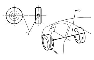
Text in Illustration *a Tread Center Mark Put tread center marks on the rearmost points of the front wheels and measure the distance between the marks (Dimension B).
-
Slowly push the vehicle straight ahead to cause the front wheels to rotate 180° using the front tire valve as a reference point.
Tech Tips
Do not allow the wheels to rotate more than 180°. If the wheels rotate more than 180°, perform the procedure from (Step A) again.
-
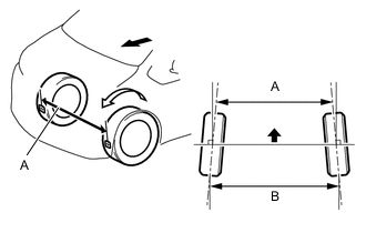
Measure the distance between the tread center marks on the front side of the wheels (Dimension A).
Text in Illustration Front of the Vehicle Toe-in (Unloaded Vehicle) Model Tire Size Engine Specified Condition Except for Rough Road Package 175/70 R14 1KR-FE B-A: 1.3 +/- 2.0 mm
(0.0512 +/- 0.0787 in.)
175/65 R15 1KR-FE B-A: 1.3 +/- 2.0 mm
(0.0512 +/- 0.0787 in.)
1NR-FE B-A: 1.3 +/- 2.0 mm
(0.0512 +/- 0.0787 in.)
175/65 R14 1KR-FE B-A: 1.3 +/- 2.0 mm
(0.0512 +/- 0.0787 in.)
185/60 R15 1KR-FE B-A: 1.3 +/- 2.0 mm
(0.0512 +/- 0.0787 in.)
1NR-FE B-A: 1.3 +/- 2.0 mm
(0.0512 +/- 0.0787 in.)
Rough Road Package 175/65 R14 1KR-FE B-A: 1.3 +/- 2.0 mm
(0.0512 +/- 0.0787 in.)
185/60 R15 1KR-FE B-A: 1.4 +/- 2.0 mm
(0.0551 +/- 0.0787 in.)
1NR-FE B-A: 1.4 +/- 2.0 mm
(0.0551 +/- 0.0787 in.)
If the toe-in is not within the specified value, adjust it at the rack ends.
-
-
INSPECT TOE-IN (for TMMF Made)
-
Bounce the vehicle up and down at the corners to stabilize the suspension.
-
Release the parking brake and move the shift lever to the neutral position.
-
Push the vehicle straight ahead approximately 5 m (16.4 ft.). (Step A)
-
Text in Illustration *a Tread Center Mark Put tread center marks on the rearmost points of the front wheels and measure the distance between the marks (Dimension B).
-
Slowly push the vehicle straight ahead to cause the front wheels to rotate 180° using the front tire valve as a reference point.
Tech Tips
Do not allow the wheels to rotate more than 180°. If the wheels rotate more than 180°, perform the procedure from (Step A) again.
-
Measure the distance between the tread center marks on the front side of the wheels (Dimension A).
Text in Illustration Front of the Vehicle Toe-in (Unloaded Vehicle) Model Tire Size Engine Specified Condition Except for Rough Road Package 175/70 R14 1KR-FE B-A: 1.3 +/- 2.0 mm
(0.0512 +/- 0.0787 in.)
1NR-FE B-A: 1.3 +/- 2.0 mm
(0.0512 +/- 0.0787 in.)
1ND-TV B-A: 1.2 +/- 2.0 mm
(0.0472 +/- 0.0787 in.)
175/65 R15 1KR-FE B-A: 1.3 +/- 2.0 mm
(0.0512 +/- 0.0787 in.)
195/50 R16 1NR-FE B-A: 1.0 +/- 2.0 mm
(0.0393 +/- 0.0787 in.)
1ND-TV B-A: 1.0 +/- 2.0 mm
(0.0393 +/- 0.0787 in.)
Except for Rough Road Package
w/ Rear Seat
175/65 R14 1KR-FE B-A: 1.3 +/- 2.0 mm
(0.0512 +/- 0.0787 in.)
Except for Rough Road Package
w/o Rear Seat
B-A: 1.3 +/- 2.0 mm
(0.0512 +/- 0.0787 in.)
Except for Rough Road Package
w/ Rear Seat
185/60 R15 1KR-FE B-A: 1.3 +/- 2.0 mm
(0.0512 +/- 0.0787 in.)
1NR-FE B-A: 1.3 +/- 2.0 mm
(0.0512 +/- 0.0787 in.)
1ND-TV B-A: 1.2 +/- 2.0 mm
(0.0472 +/- 0.0787 in.)
Except for Rough Road Package
w/o Rear Seat
1KR-FE B-A: 1.3 +/- 2.0 mm
(0.0512 +/- 0.0787 in.)
1NR-FE B-A: 1.3 +/- 2.0 mm
(0.0512 +/- 0.0787 in.)
1ND-TV B-A: 1.2 +/- 2.0 mm
(0.0472 +/- 0.0787 in.)
Except for Rough Road Package
w/o Panorama Roof
175/65 R15 1NR-FE B-A: 1.3 +/- 2.0 mm
(0.0512 +/- 0.0787 in.)
1ND-TV B-A: 1.2 +/- 2.0 mm
(0.0472 +/- 0.0787 in.)
Except for Rough Road Package
w/ Panorama Roof
1NR-FE B-A: 1.0 +/- 2.0 mm
(0.0393 +/- 0.0787 in.)
1ND-TV B-A: 1.0 +/- 2.0 mm
(0.0393 +/- 0.0787 in.)
Rough Road Package 175/65 R14 1KR-FE B-A: 1.3 +/- 2.0 mm
(0.0512 +/- 0.0787 in.)
185/60 R15 1KR-FE B-A: 1.4 +/- 2.0 mm
(0.0551 +/- 0.0787 in.)
1NR-FE B-A: 1.4 +/- 2.0 mm
(0.0551 +/- 0.0787 in.)
1ND-TV B-A: 1.3 +/- 2.0 mm
(0.0512 +/- 0.0787 in.)
If the toe-in is not within the specified value, adjust it at the rack ends.
-
-
-
REAR WHEEL ALIGNMENT
-
INSPECT CAMBER (for TMC Made)
-
Install the camber-caster-kingpin gauge and position the rear wheel on the alignment tester.
-
Inspect the camber.
Camber (Unloaded Vehicle) Model Tire Size Camber Right - Left Error Except for Rough Road Package 175/70 R14 -0°57' +/- 30'
(-0.95° +/- 0.5°)
0°30'
(0.5°)
175/65 R15 175/65 R14 185/60 R15 Rough Road Package 175/65 R14 -0°54' +/- 30'
(-0.90° +/- 0.5°)
185/60 R15 Note
The tolerance for the difference between the left and right wheels is 30' (0.5°) or less for both cambers. If the camber is not within the specified range, inspect the suspension parts and replace them if necessary.
-
-
INSPECT CAMBER (for TMMF Made)
-
Install the camber-caster-kingpin gauge and position the rear wheel on the alignment tester.
-
Inspect the camber.
Camber (Unloaded Vehicle) Model Tire Size Camber Right - Left Error Except for Rough Road Package 175/70 R14 -0°57' +/- 30'
(-0.95° +/- 0.5°)
0°30'
(0.5°)
175/65 R15 195/50 R16 Except for Rough Road Package
w/ Rear Seat
175/65 R14 -0°57' +/- 30'
(-0.95° +/- 0.5°)
Except for Rough Road Package
w/o Rear Seat
-0°56' +/- 30'
(-0.93° +/- 0.5°)
Except for Rough Road Package
w/ Rear Seat
185/60 R15 -0°57' +/- 30'
(-0.95° +/- 0.5°)
Except for Rough Road Package
w/o Rear Seat
-0°56' +/- 30'
(-0.93° +/- 0.5°)
Except for Rough Road Package
w/o Panorama Roof
175/65 R15 -0°57' +/- 30'
(-0.95° +/- 0.5°)
Except for Rough Road Package
w/ Panorama Roof
Rough Road Package 175/65 R14 -0°54' +/- 30'
(-0.90° +/- 0.5°)
185/60 R15 Note
The tolerance for the difference between the left and right wheels is 30' (0.5°) or less for both cambers. If the camber is not within the specified range, inspect the suspension parts and replace them if necessary.
-
-
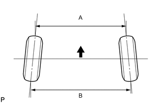
INSPECT TOE-IN (for TMC Made)
Text in Illustration Front Toe-in (Unloaded Vehicle) Model Tire Size B - A Except for Rough Road Package 175/70 R14 3.9 +/- 3.0 mm
(0.154 +/- 0.118 in.)
175/65 R15 3.9 +/- 3.0 mm
(0.154 +/- 0.118 in.)
175/65 R14 3.4 +/- 3.0 mm
(0.134 +/- 0.118 in.)
185/60 R15 3.6 +/- 3.0 mm
(0.142 +/- 0.118 in.)
Rough Road Package 175/65 R14 2.7 +/- 3.0 mm
(0.106 +/- 0.118 in.)
185/60 R15 2.8 +/- 3.0 mm
(0.110 +/- 0.118 in.)
If the toe-in is not within the specified range, inspect the suspension parts and replace them if necessary.
-
INSPECT TOE-IN (for TMMF Made)
Text in Illustration Front Toe-in (Unloaded Vehicle) Model Tire Size B - A Except for Rough Road Package 175/70 R14 3.9 +/- 3.0 mm
(0.154 +/- 0.118 in.)
175/65 R15 3.9 +/- 3.0 mm
(0.154 +/- 0.118 in.)
195/50 R16 3.9 +/- 3.0 mm
(0.154 +/- 0.118 in.)
Except for Rough Road Package
w/ Rear Seat
175/65 R14 3.4 +/- 3.0 mm
(0.134 +/- 0.118 in.)
Except for Rough Road Package
w/o Rear Seat
3.3 +/- 3.0 mm
(0.130 +/- 0.118 in.)
Except for Rough Road Package
w/ Rear Seat
185/60 R15 3.6 +/- 3.0 mm
(0.142 +/- 0.118 in.)
Except for Rough Road Package
w/o Rear Seat
3.4 +/- 3.0 mm
(0.134 +/- 0.118 in.)
Except for Rough Road Package
w/o Panorama Roof
175/65 R15 3.9 +/- 3.0 mm
(0.154 +/- 0.118 in.)
Except for Rough Road Package
w/ Panorama Roof
Rough Road Package 175/65 R14 2.7 +/- 3.0 mm
(0.106 +/- 0.118 in.)
185/60 R15 2.8 +/- 3.0 mm
(0.110 +/- 0.118 in.)
If the toe-in is not within the specified range, inspect the suspension parts and replace them if necessary.
-