FRONT SIDE MEMBER CUT AND JOIN REPLACEMENT SECTIONS (SMALL AREAS)
-
With the radiator side support removed.
-
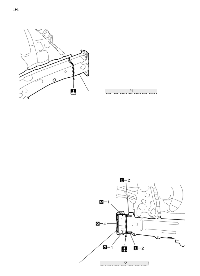
REMOVAL
Symbol Meaning 
Remove Weld Points 
Remove Weld Points 
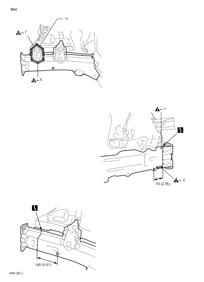
Cut and Join Location
-
After removing the *1, remove the member.
-
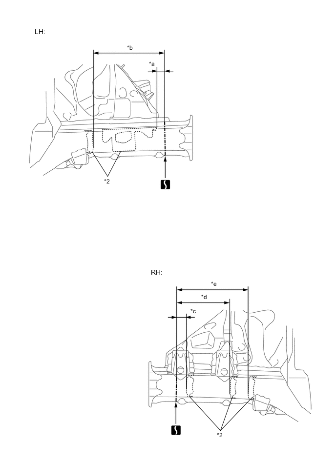
Carefully cut the member so not to damage *2.
REMOVAL POINT
Reference Value Area Measurement Area Measurement *a 30 mm (1.18 in.) *b 310 mm (12.20 in.) *c 47 mm (1.85 in.) *d 232 mm (9.13 in.) *e 310 mm (12.20 in.) - - 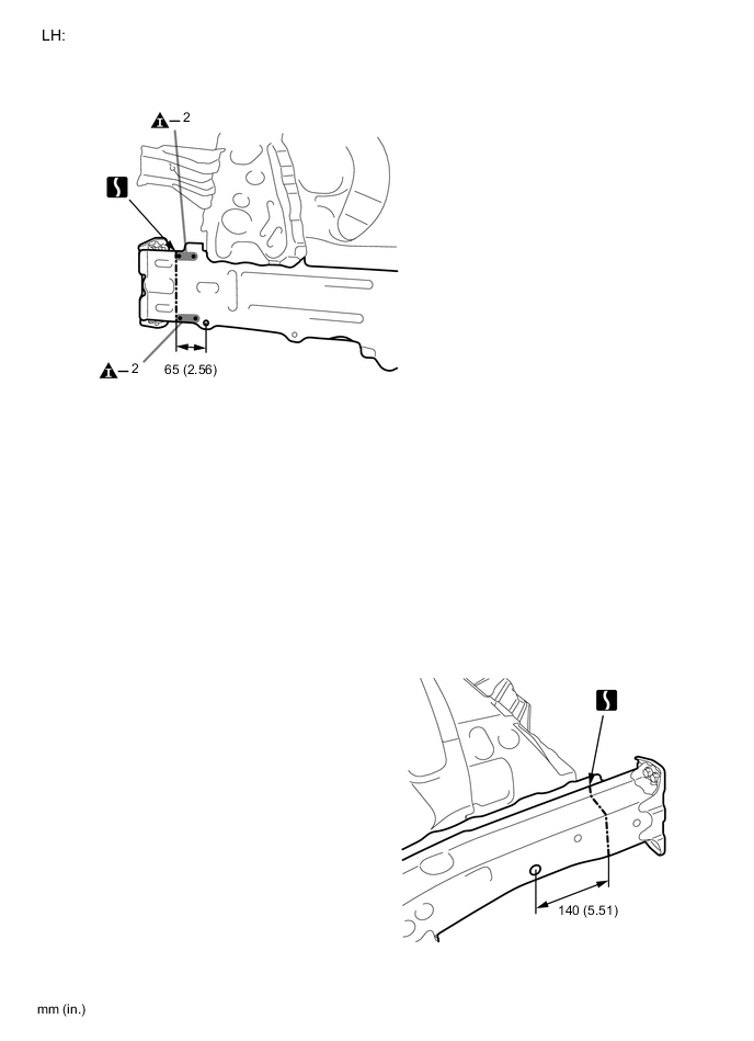
-
-
INSTALLATION
Symbol Meaning Remove Weld Points 
Plug Weld 
Plug Weld Cut and Join Location 
Butt Weld
-
Temporarily install the new parts and measure each part of the new parts in accordance with the body dimension diagram. (See the body dimensions)
-
Divide a new part of front side member reinforcement in to *1 and *2 at the weld points. After welding the *2 to the vehicle side, install the *1.
-
After applying the top coat, apply anti-rust agent to the internal panel portion of the closed section structural weld points.
INSTALLATION POINT
*1 FRONT SIDE MEMBER REINFORCEMENT *2 FRONT SIDE MEMBER PLATE OUTER 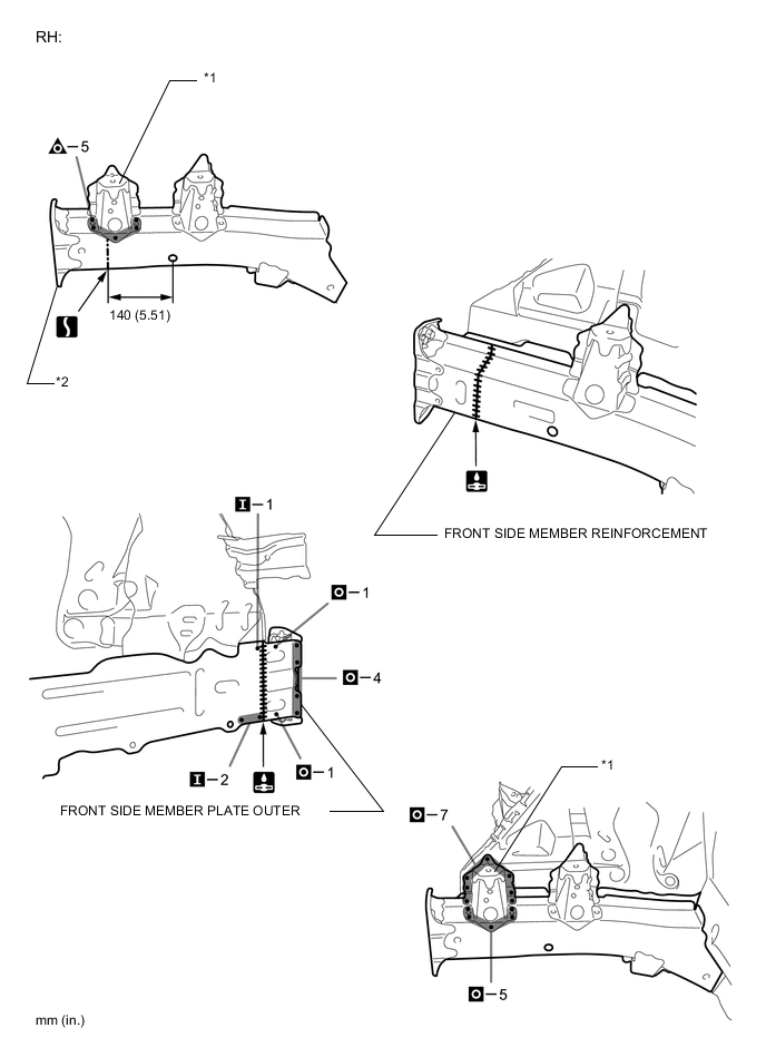
-