ROCKER PANEL CUT AND JOIN REPLACEMENT SECTIONS
- Weld work for 980 MPa ultra high strength steel
-
*1: When welding 2 panels together including 980 MPa ultra high strength steel.
Spot weld Pressure 2940 N (300 kgf, 661 lbf) Weld current 10000 A Weld time 16 Cyc. (0.27 Sec.) Plug weld Plug diameter 10 mm (0.39 in.) Wire type AWS A5.18 ER70S-3 Shield gas Metal active gas
Follow the welding conditions below when welding ultra high strength steel to assure sufficient weld strength. (When repairing this model)
-
*2: When welding more than 3 panels together including 980 MPa ultra high strength steel. (When plug welding a panel to the welded panels with the weld condition above.)
Plug weld Plug diameter Same as the standard method (See the introduction) Wire type AWS A5.18 ER70S-3 Shield gas Metal active gas
Note
Be sure to use Metal active gas (Ar 80% + CO220%) as the shield gas when plug welding. Sufficient weld strength cannot be assured when using 100% CO2shield gas.
-
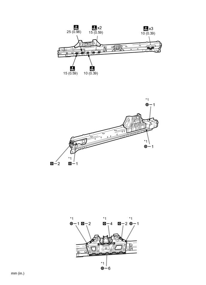
REMOVAL
Symbol meaning 
Remove Weld Points 
Remove Weld Points 
Remove Weld Points 
Cut with Disc Sander etc. 
Cut and Join Location 
Cut Location for Supply Parts
-
Do not butt weld or heat repair because the heat decreases the strength of areas where ultra high strength steel is used. (See the introduction)
-
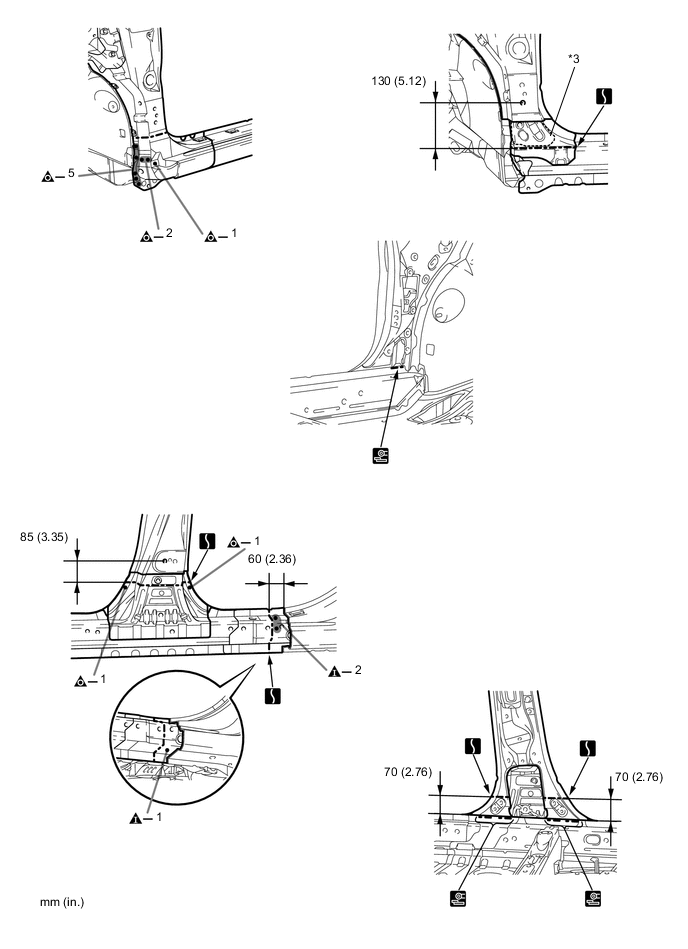
Carefully cut the front body pillar lower reinforce so not to damage *3.
REMOVAL POINT
-
-
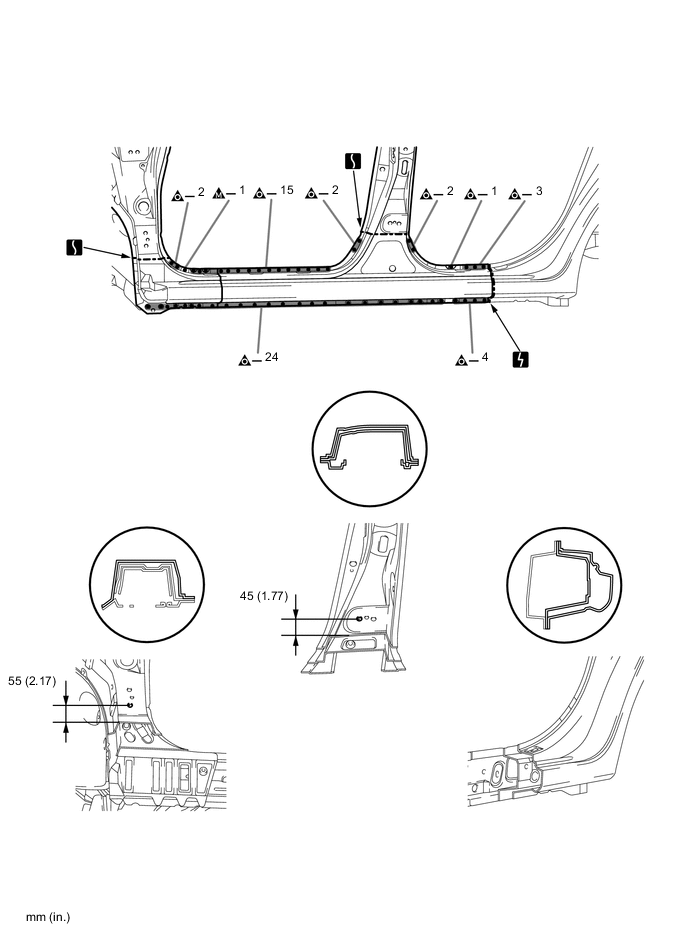
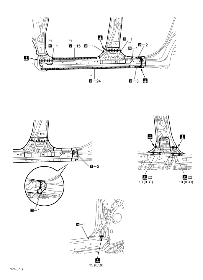
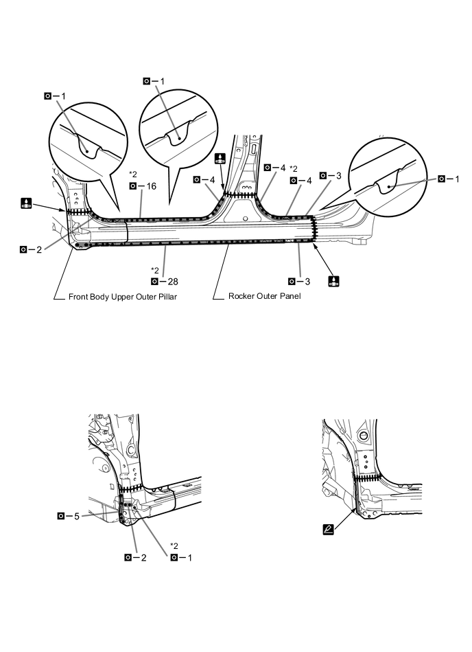
INSTALLATION
Symbol meaning Remove Weld Points 
Spot Weld 
Plug Weld 
Plug Weld 
Plug Weld Cut and Join Location 
Fillet Weld 
Butt Weld 
Body Sealer
-
Inspect the fitting of the related parts around the new parts before welding. This affects the appearance of the finish.
-
Temporarily install the new parts and measure each part of the new parts in accordance with the body dimension diagram. (See the body dimension diagram)
-
If the entire supply part is not needed, remove the part of the supply part that is needed.
-
Before installing a new part, apply body sealer.
Tech Tips
Apply body sealer in an even, continuous bead.
-
Follow the welding conditions when welding *1 and *2 to assure sufficient weld strength. (See the introduction)
-
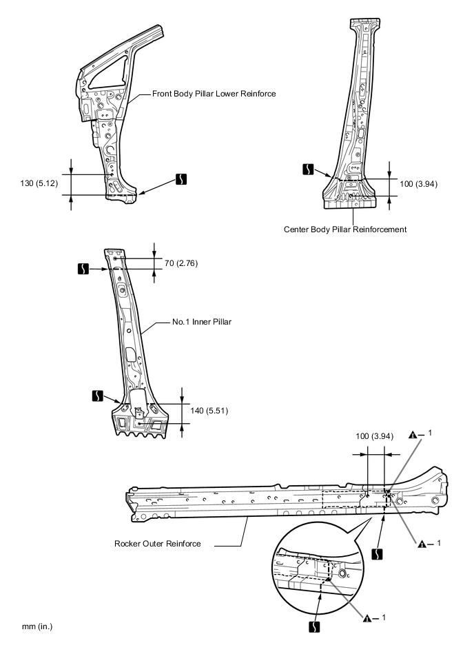
Before temporarily installing the new parts, weld the rocker outer reinforce, front body pillar lower reinforce, center body pillar reinforcement and No. 1 inner pillar with the standard number of welding points.
-
After welding the rocker outer reinforce, front body pillar lower reinforce, center body pillar reinforcement and No. 1 inner pillar to the vehicle side, install the front body upper outer pillar and rocker outer panel.
-
After welding, apply body sealer and undercoating to the corresponding parts. (See the paint / coating)
-
After applying the top coat, apply anti-rust agent to the internal panel portion of the closed section structural weld points.
INSTALLATION POINT
-