FIT STANDARD / ADJUSTMENT METHOD ADJUSTMENT
-
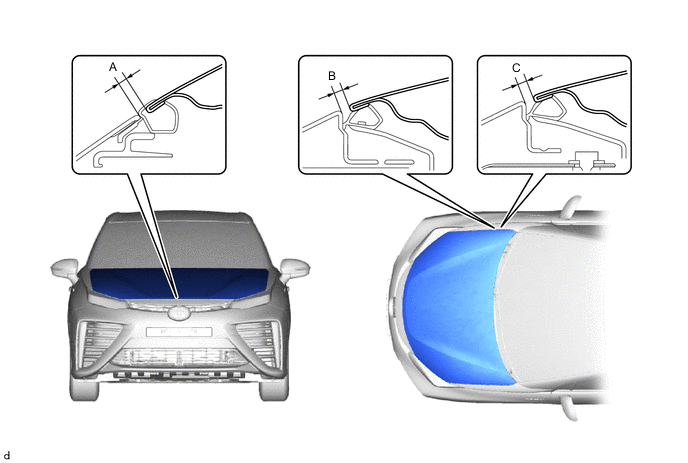
INSPECT HOOD SUB-ASSEMBLY
-
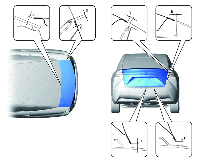
Check that the clearance measurements of areas "A" though "C" are within each standard range.
Tech Tips
Centering bolts are used to mount the hood hinge and hood lock assembly. The hood and hood lock assembly cannot be adjusted with the centering bolts installed. Substitute the centering bolts with standard bolts when making adjustments.
-
-
ADJUST HOOD SUB-ASSEMBLY
-
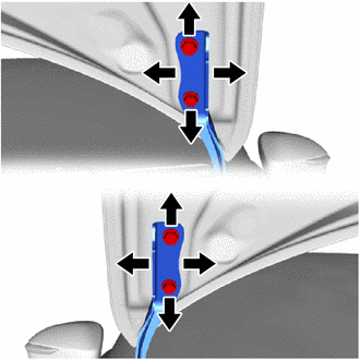
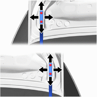
Horizontally and vertically adjust the hood.
-
Loosen the 4 hinge bolts of the hood.
-
Adjust the clearance between the hood and front fender by moving the hood.
-
Tighten the 4 hinge bolts after adjustment.
- Torque:
- 13 N*m { 133 kgf*cm, 10 ft.*lbf }
-
-
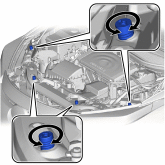
Adjust the height of the front end of the hood using the hood bumper cushions.
-
Adjust the 2 hood bumper cushions so that the heights of the hood and fenders are aligned.
-
-
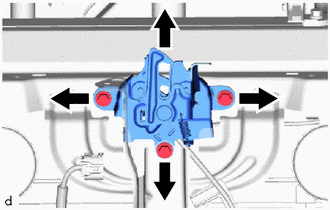
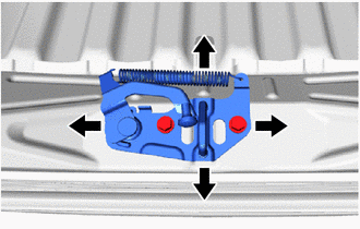
Adjust the hood lock assembly.
-
Loosen the 3 bolts.
-
Adjust the hood lock assembly and tighten the 3 bolts.
- Torque:
- 8.0 N*m { 82 kgf*cm, 71 in.*lbf }
-
-
-
INSPECT FRONT DOOR PANEL SUB-ASSEMBLY
-
Check that the clearance measurements of areas "A" through "N" are within each standard range.
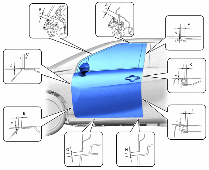
Tech Tips
-
Use the same procedure for the RHD and LHD vehicles.
-
The procedure listed below is for the LHD vehicles.
-
Use the same procedure for the RH and LH sides.
-
The procedure listed below is for the LH side.
-
Centering bolts are used to mount the door hinge to the vehicle body and door. The door cannot be adjusted with the centering bolts on. Substitute the centering bolts for standard bolts when making adjustments.
-
-
ADJUST FRONT DOOR PANEL SUB-ASSEMBLY
-
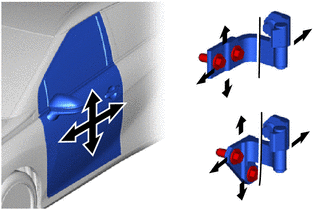
Using SST, adjust the door horizontally and vertically by loosening the 4 body side hinge bolts.
- SST
- 09812-00010
-
Tighten the 4 body side hinge bolts after the adjustment.
- Torque:
- 32.5 N*m { 331 kgf*cm, 24 ft.*lbf }
-
Adjust the door horizontally and vertically by loosening the 2 door side hinge bolts.
-
Tighten the 2 door side hinge bolts after the adjustment.
- Torque:
- 32.5 N*m { 331 kgf*cm, 24 ft.*lbf }
-
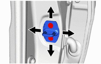
Using a T40 "TORX" socket wrench, slightly loosen the 2 striker mounting screws.
-
Using a brass bar and a hammer, hit the striker to adjust its position.
-
Using a T40 "TORX" socket wrench, tighten the 2 striker mounting screws after adjustment.
- Torque:
- 23 N*m { 235 kgf*cm, 17 ft.*lbf }
-
-
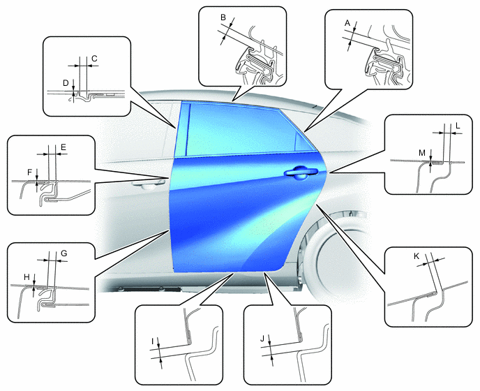
INSPECT REAR DOOR PANEL SUB-ASSEMBLY
-
Check that the clearance measurements of areas "A" through "M" are within each standard range.
Tech Tips
-
Use the same procedure for the RH and LH sides.
-
The procedure listed below is for the LH side.
-
Centering bolts are used to mount the door hinge to the vehicle body and door. The door cannot be adjusted with the centering bolts on. Substitute the centering bolts for standard bolts when making adjustments.
-
-
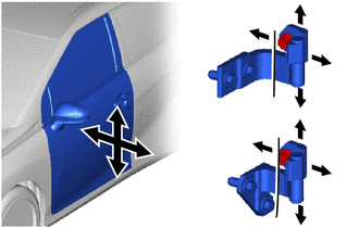
ADJUST REAR DOOR PANEL SUB-ASSEMBLY
-
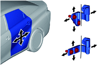
Using SST, adjust the door horizontally and vertically by loosing the 4 body side hinge bolts.
- SST
- 09812-00010
-
Tighten the 4 body side hinge bolts after the adjustment.
- Torque:
- 32.5 N*m { 331 kgf*cm, 24 ft.*lbf }
-
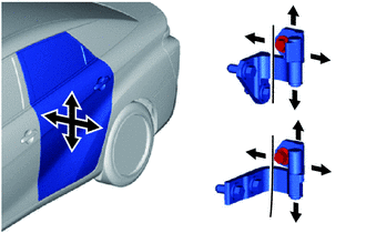
Adjust the door horizontally and vertically by loosing the 2 body side hinge bolts.
-
Tighten the 2 body side hinge bolts after the adjustment.
- Torque:
- 32.5 N*m { 331 kgf*cm, 24 ft.*lbf }
-
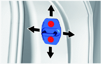
Using a T40 "TORX" socket wrench, slightly loosen the 2 striker mounting screws.
-
Using a brass bar and a hammer, hit the striker to adjust its position.
-
Using a T40 "TORX" socket wrench, tighten the 2 striker mounting screws after adjustment.
- Torque:
- 23 N*m { 235 kgf*cm, 17 ft.*lbf }
-
-
INSPECT LUGGAGE COMPARTMENT DOOR PANEL SUB-ASSEMBLY
-
Check that the clearance measurements of areas "A" through "G" are within each standard range.
-
-
ADJUST LUGGAGE COMPARTMENT DOOR PANEL SUB-ASSEMBLY
-
Loosen the hinge bolts to adjust the door horizontally and vertically.
-
Tighten the hinge bolts after adjustment.
- Torque:
- 7.0 N*m { 71 kgf*cm, 62 in.*lbf }
-
Loosen the striker mounting bolts.
-
Using a brass bar and a hammer, hit the striker to adjust its position.
-
Tighten the striker mounting bolts after adjustment.
- Torque:
- 5.5 N*m { 56 kgf*cm, 49 in.*lbf }
-