REAR FLOOR SIDE MEMBER ASSEMBLY REPLACEMENT
-
With the rear floor lower front crossmember assembly removed.
-
REMOVAL
Symbol Meaning 
Remove Weld Points 
Remove Weld Points 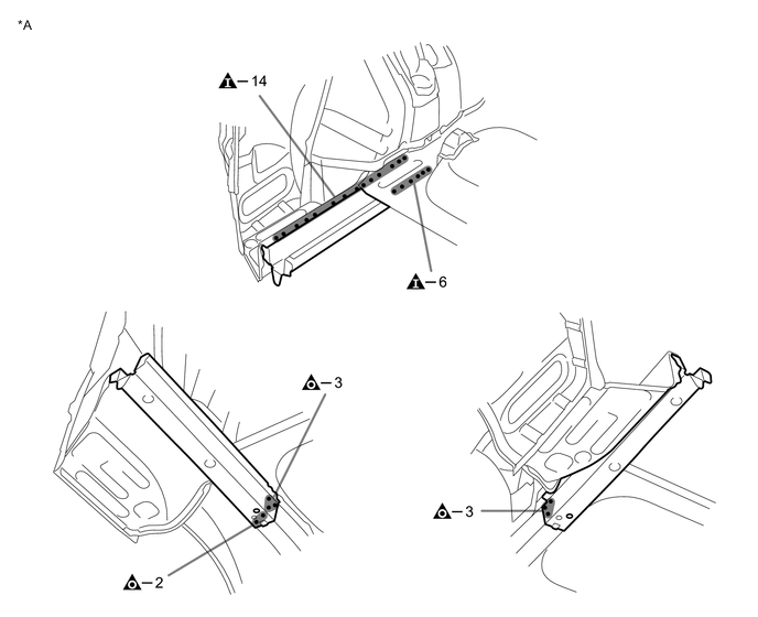
*A LH - - 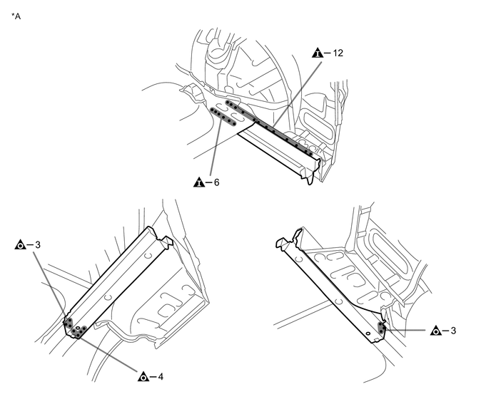
*A RH - - -
INSTALLATION
Symbol Meaning 
Remove Weld Points 
Remove Weld Points 
Assembly Mark
-
Temporarily install the new parts and measure each part of the new parts in accordance with the body dimension diagram. (See the body dimensions)
-
For positioning of the new parts, align the installation standard holes of the rear floor side member sub-assembly rear and the member.
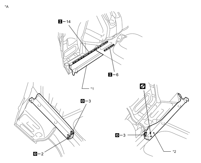
*A LH - - *1 REAR FLOOR SIDE MEMBER SUB-ASSEMBLY REAR *2 WELD BOLT 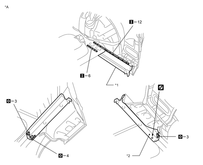
*A RH - - *1 REAR FLOOR SIDE MEMBER SUB-ASSEMBLY REAR *2 WELD BOLT -
After welding, apply body sealer and undercoating to the corresponding parts. (See the painting/coating)
-
After applying the top coat, apply anti-rust agent to the internal panel portion of the closed section structural weld points.
-