WORK NOTICES AND PRECAUTIONS ENSURING SAFETY AND QUALITY DURING BODY REPAIR OF FUEL CELL VEHICLE
When repairing the body panels, the same procedures are used as for conventional vehicles. However, when performing work that involves the removal and installation of exclusive parts, such as the hydrogen tanks, hydrogen tank tubes and fuel cell, or performing work in the areas around these parts, there are special precautions unique to FCV that must be taken. Perform work safely by always following the procedures described in this manual, the owner's manual and the electronic technical manual (repair manual).
-
MAIN PARTS AND PRECAUTIONS FOR FCV
Characteristics and Precautions by System (○: Applicable) Main Parts Hydrogen-related FC Cooling System Intake System High-voltage System 1. FC Radiator (Main, Sub) Characteristics:
-
Hydrogen gas
-
High-pressure gas
-
Fiber-reinforced plastic tank
-
Precision parts
↓
Precautions:
-
Hydrogen safety
-
High-pressure safety
-
Preserving air tightness
-
Entry of foreign matter
○ Characteristics:
-
Exclusive coolant (FCC)
-
Non-reusable parts
-
Precision parts
↓
Precautions:
-
Incorrect addition of fluid
-
Non-reusable parts
-
Entry of foreign matter
The motor system uses conventional LLC (2 types of coolant)
Characteristics:
-
Precision parts
↓
Precautions:
-
Entry of foreign matter
Characteristics:
-
High-voltage
-
Precision parts
-
2 service plug grips
↓
Precautions:
-
High-voltage safety
2. Cooling Water Pipes ○ 3. FC Cooling Water Pump ○ ○ 4. FC Cooling Water Ion Exchanger ○ 5. Air Cleaner ○ 6. FC Air Compressor ○ ○ 7. Intercooler ○ 8. Inverter / Converter ○ 9. FCV Transaxle ○ 10. FC Stack ○ ○ ○ ○ 11. High-voltage Frame Wire ○ 12. Hydrogen Pump ○ ○ 13. EV Battery ○ 14. Hydrogen Tank ○ 15. Hydrogen Tank Tubes / Hydrogen Supply Regulator ○ 16. Hydrogen Inlet Receptacle ○ -
-
MAIN PRECAUTIONS FOR BODY REPAIR
Procedures Precautions Welding or cutting (sparks or cutting fragments) Do not allow sparks or hot fragments from cutting to contact the hydrogen tanks, hydrogen tank tubes , etc. Applying paint, putty, etc. (solvents) Do not allow solvents to contact the hydrogen tanks, etc. Sanding (dust) Do not allow dust or mist to enter the hydrogen, cooling or intake systems. Applying paint or anti-corrosive coating (mist) Drying paint or putty (heat) Do not place a far infrared panel near the hydrogen tanks or hydrogen tank tubes (to prevent abnormal temperature increases). As with other vehicles (other fuel types), a painting booth can only be used when there are no leaks. -
SPECIAL PRECAUTIONS FOR BODY REPAIR UNIQUE TO FCV
-
Working with hydrogen
Figure 1. Parts Location
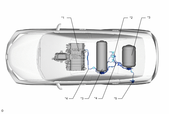
*1 FC Stack *2 Hydrogen Supply Regulator *3 Hydrogen Tank *4 Hydrogen Tank Tubes *5 Hydrogen Inlet Receptacle - - Note
When installing a hydrogen tank tube, always use the tank removal and installation guide tool to align the connections.
Tech Tips
The following are examples of procedures that are often performed.
-
Replacements or repairs including the left quarter panel (wheel house)
-
Replacement or repair of the lower back panel or rear floor panel
○: Performed (○): Performed according to damage or part to be repaired Vehicle Brought to Workshop Estimation Waiting for Repairs Disassembly Body Repair Vehicle Restoration Final Inspection Overall *1 Ensure ventilation in the workplace ○ ○ ○ ○ ○ ○ ○ *2 Check for leaks at connections and damaged areas
-
Use a hydrogen gas detector
○ (○) (○) (○) (○) ○ *3 Check for leaks after repairs
-
First inspection: Check for leaks using a 10 MPa nitrogen gas injector
-
Second inspection: Check for leaks with hydrogen at 70 MPa (refuel at a hydrogen station)
(○) (○) *4 Inspect with a hydrogen detector
-
Perform an inspection using hydrogen gas for inspection (specialized gas)
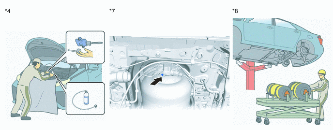
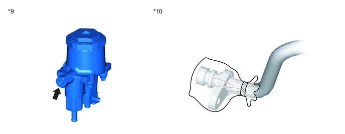
(○) (○) Hydrogen Tank *5 Do not allow sparks or solvents to contact the hydrogen tank because it is made of plastic ○ ○ ○ *6 Do not expose the hydrogen tank to high temperatures (85°C or above) ○ *7 Shut off hydrogen using the manual valve (○) (○) (○) (○) (○) (○) *8 Use the "tank removal and installation guide tool" ○ ○ Hydrogen Tank Tubes *9 Release pressure before removal because the hydrogen tank tube is under high pressure
-
Release pressure from the medium pressure leak check port of the regulator (vehicle part)
○ *10 Prevent the entry of foreign matter during installation and removal
-
In order to prevent the entry of foreign matter, cover removed parts with a new plastic bag, etc.
○ ○ ○ *11 Do not reuse the high-pressure pipe ○ *12 Use the "tank removal and installation guide tool" when connecting the hydrogen tank tube to align the connections ○ 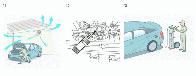
-
-
Working with high voltage
Figure 2. Parts Location
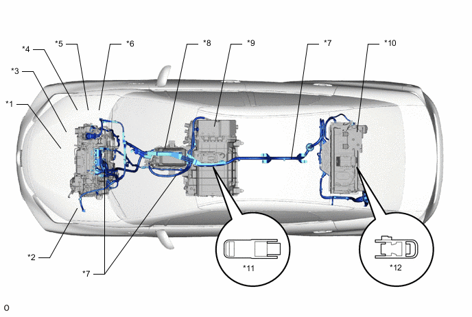
*1 W/Converter Inverter *2 FCV W/Motor Transaxle *3 W/Motor Compressor Cooler Compressor *4 FC Air Compressor *5 FC Cooling Water Pump *6 Electric Heater *7 High-voltage Frame Wire *8 FC Converter *9 FC Stack *10 EV Battery *11 FC Stack Service Plug Grip *12 Service Plug Grip (for EV) Tech Tips
The following are examples of procedures that are often performed.
-
Front: Body repair around the inverter or FCV w/motor transaxle
-
Rear: Body repair around the EV battery
○: Performed (○): Performed according to damage or part to be repaired Vehicle Brought to Workshop Estimation Waiting for Repairs Disassembly Body Repair Vehicle Restoration Final Inspection *1 Removal of the service plug grips
-
This procedure is fundamentally the same as for hybrid vehicles, but because there are 2 service plug grips, make sure to remove both
(○) (○) ○ ○ ○ -
-
Working with FC cooling systems
Figure 3. Parts Location
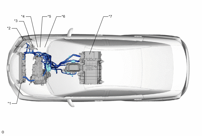
*1 FC Radiator *2 FC Sub-radiator *3 FC Cooling Water Ion Exchanger *4 FC Cooling Water Pump *5 Electric Heater *6 Heater Water Pump *7 FC Stack - - Tech Tips
-
Colorless, clear FCC (Toyota genuine FC stack coolant) with insulating properties is used. (Conventional red LLC is used to cool the motor system.)
-
The following are examples of procedures that are often performed.
-
Body repair around the radiator support
-
Body repair around the front fender apron
○: Performed (○): Performed according to damage or part to be repaired Vehicle Brought to Workshop Estimation Waiting for Repairs Disassembly Body Repair Vehicle Restoration Final Inspection *1 To prevent the entry of foreign matter, do not reuse FCC (TOYOTA genuine FC stack coolant) Dispose ○ *2 Do not fill with water, conventional LLC, etc., even in small quantities ○ *3 In order to prevent the entry of foreign matter, cover removed parts with a new plastic bag, etc. (○) ○ ○ ○ 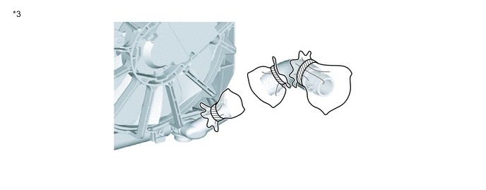
-
-
Working with FC air systems
Figure 4. Parts Location
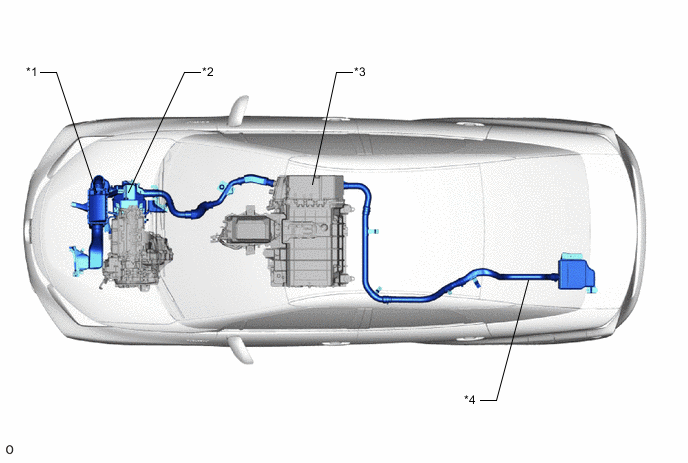
*1 Air Cleaner with Element *2 FC Air Compressor with Motor *3 FC Stack *4 FC Exhaust Tail Pipe Tech Tips
-
The following are examples of procedures that are often performed.
-
Body repair around the radiator support
-
Body repair around the front fender apron
○: Performed (○): Performed according to damage or part to be repaired Vehicle Brought to Workshop Estimation Waiting for Repairs Disassembly Body Repair Vehicle Restoration Final Inspection *1 In order to prevent the entry of foreign matter, cover removed parts with a new plastic bag, etc. (○) ○ ○ ○ *2 Do not start the vehicle with the air cleaner removed ○ ○ 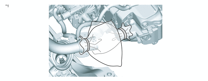
-
-