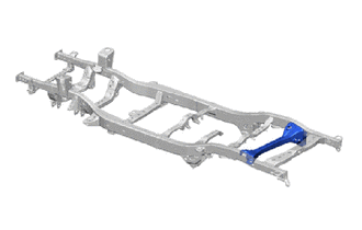
FRAME REAR FRONT CROSSMEMBER ASSEMBLY REPLACEMENT
-
With the frame rear crossmember assembly removed.
Tech Tips
-
Use the same procedure for the RH side and LH side.
-
The procedure listed below is for the RH side.
-
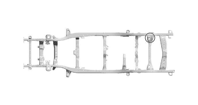
REMOVAL
Symbol Meaning 
Cut with Disc Sander etc. 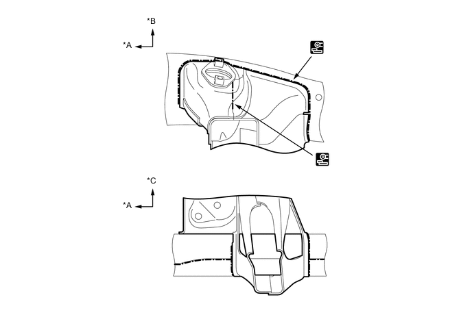
*A FRONT *B UPPER *C LH - - 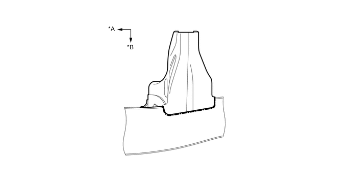
*A FRONT *B UPPER 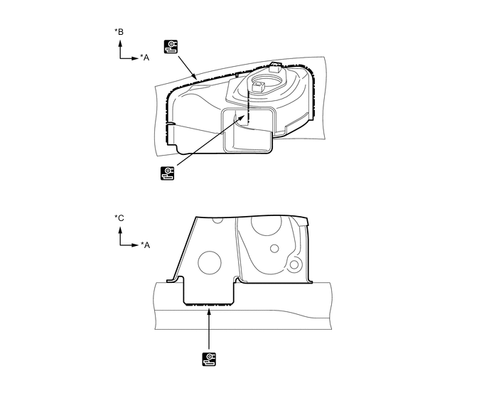
*A FRONT *B UPPER *C RH - - -
INSTALLATION
Symbol Meaning 
Fillet Weld
-
Make sure that proper welding can be performed by setting up the welding conditions as necessary before performing work.
-
To prevent heat deformation, weld the right and left side of each part before continuing to the next part.
-
Make sure that the welding bead at A is overlapped.
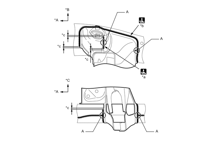
*A FRONT *B UPPER *C LH - - *a 47 mm (1.85 in.) *b 656 mm (25.83 in.) *c 5 +/- 5 mm (0.20 +/- 0.20 in.) - - -
Make sure that the welding bead at A is overlapped.
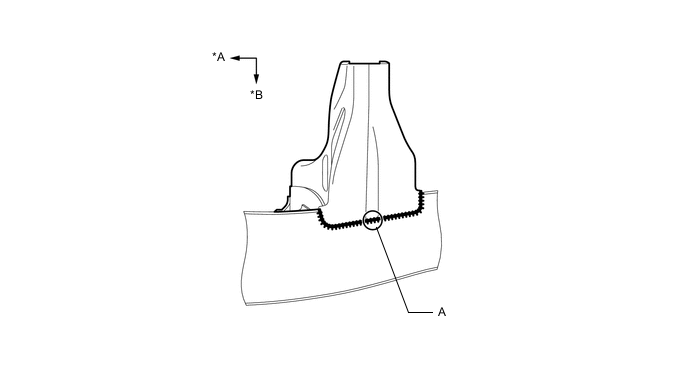
*A FRONT *B UPPER -
Make sure that the welding bead at A is overlapped.
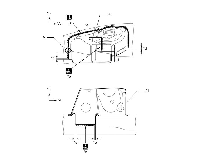
*A FRONT *B UPPER *C RH - - *1 FRAME CROSSMEMBER SUB-ASSEMBLY NO.6 - - *a 358 mm (14.09 in.) *b 47 mm (1.85 in.) *c 70 mm (2.76 in.) *d 5 +/- 5 mm (0.20 +/- 0.20 in.) *e 3 +/- 5 mm (0.12 +/- 0.20 in.) - - -
After applying the top coat, apply anti-rust agent to the internal panel portion of the closed section structural weld points.
-