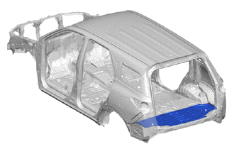
REAR FLOOR PAN CUT AND JOIN REPLACEMENT SECTIONS
-
With the body lower back panel cut and join replacement sections (small areas) and rear floor crossmember upper gusset assembly removed.
-
REMOVAL
Symbol Meaning 
Remove Weld Points 
Remove Weld Points 
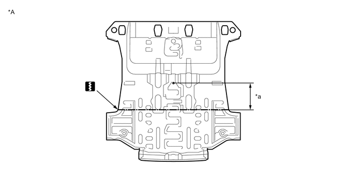
Cut Location 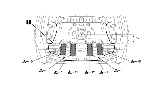
*a 305 mm (12.01 in.) - - 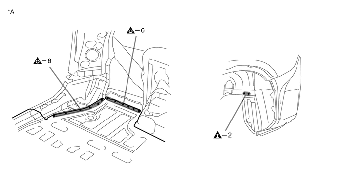
*A LH Side - - 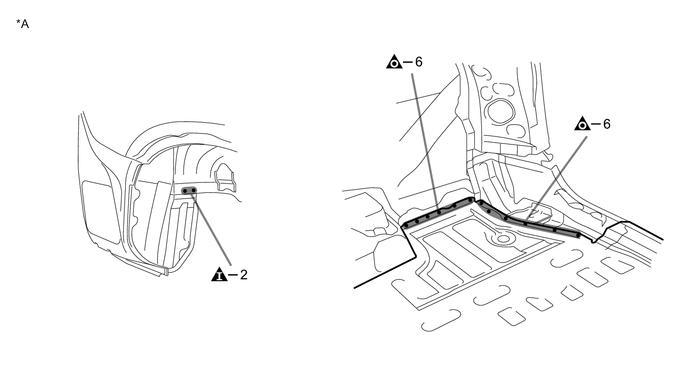
*A RH Side - - -
INSTALLATION
Symbol Meaning 
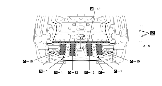
Plug Weld 
Plug Weld Cut Location 
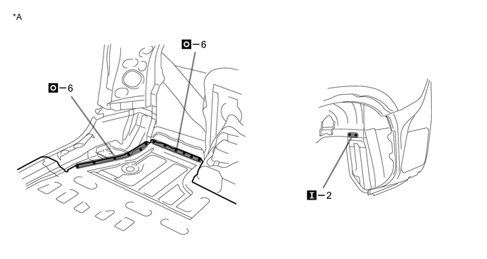
Body Sealer
-
Cut the new part so that it overlaps the previous cut location by approximately 20 mm (0.79 in.).
*A Upper Face - - *a 285 mm (11.22 in.) - - -
Before temporarily installing the new parts, weld the rear floor pan and body lower back panel reinforce sub-assembly with the standard number of welding points.
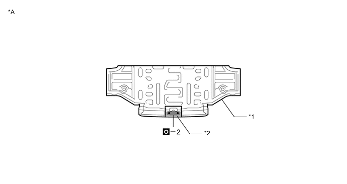
*A Lower Face - - *1 REAR FLOOR PAN *2 BODY LOWER BACK PANEL REINFORCE SUB-ASSEMBLY -
Perform plug-welding in the area where the panel are overlapped. Apply body sealer to both sides of each panel.
Tech Tips
-
Confirm that the panels are securely welded together.
-
Apply body sealer in an even, continuous bead.
*A LH Side - - 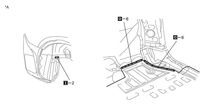
*A RH Side - - -
-
After welding, apply body sealer and undercoating to the corresponding parts. (See the painting/coating)
-
After applying the top coat, apply anti-rust agent to the internal panel portion of the closed section structural weld points.
-