WORK NOTICES AND PRECAUTIONS PRECAUTIONS FOR SRS AIRBAG SYSTEM
-
HANDLING OF A VEHICLE THAT HAS BEEN DAMAGED IN A COLLISION
-
Refer to the TOYOTA Repair Manual for the SRS airbag system inspection procedures.
-
If impacts are likely to occur to the front airbag sensors, door side airbag sensors, side airbag sensor assemblies or airbag sensor assembly remove each sensor as necessary beforehand.
-
Do not allow the front airbag sensors, door side airbag sensors, side airbag sensor assemblies or airbag sensor assembly to become heated to high temperatures.
-
Check the wire harnesses and connectors for damage and/or melting, as some areas of the airbags and seat belt pretensioners may heat up to several hundred degrees when they operate.
-
-
PRECAUTIONS FOR USING ELECTRIC WELDER
-
Check the Diagnostic Trouble Codes (DTCs).
-
If one or more DTCs are displayed:
-
Disconnect the negative (-) terminal cable from the battery.
-
Disconnect all the malfunctioning circuit connectors.
-
Disconnect the airbag sensor assembly connector.
-
-
If DTCs are NOT displayed:
-
Inspect for damage to the electric wiring harnesses and connectors.
-
Disconnect the negative (-) terminal cable from the battery.
-
Disconnect the airbag sensor assembly connector.
-
-
-
-
PARTS LOCATION
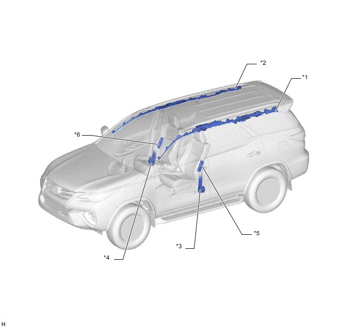
*1 CURTAIN SHIELD AIRBAG ASSEMBLY LH *2 CURTAIN SHIELD AIRBAG ASSEMBLY RH *3 FRONT SEAT OUTER BELT ASSEMBLY LH *4 FRONT SEAT OUTER BELT ASSEMBLY RH *5 FRONT SEAT AIRBAG ASSEMBLY LH *6 FRONT SEAT AIRBAG ASSEMBLY RH 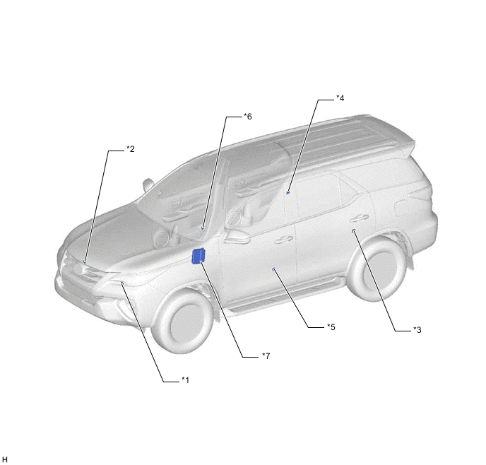
*1 FRONT AIRBAG SENSOR LH *2 FRONT AIRBAG SENSOR RH *3 SIDE AIRBAG SENSOR ASSEMBLY LH *4 SIDE AIRBAG SENSOR ASSEMBLY RH *5 DOOR SIDE AIRBAG SENSOR LH *6 DOOR SIDE AIRBAG SENSOR RH *7 ECM - - 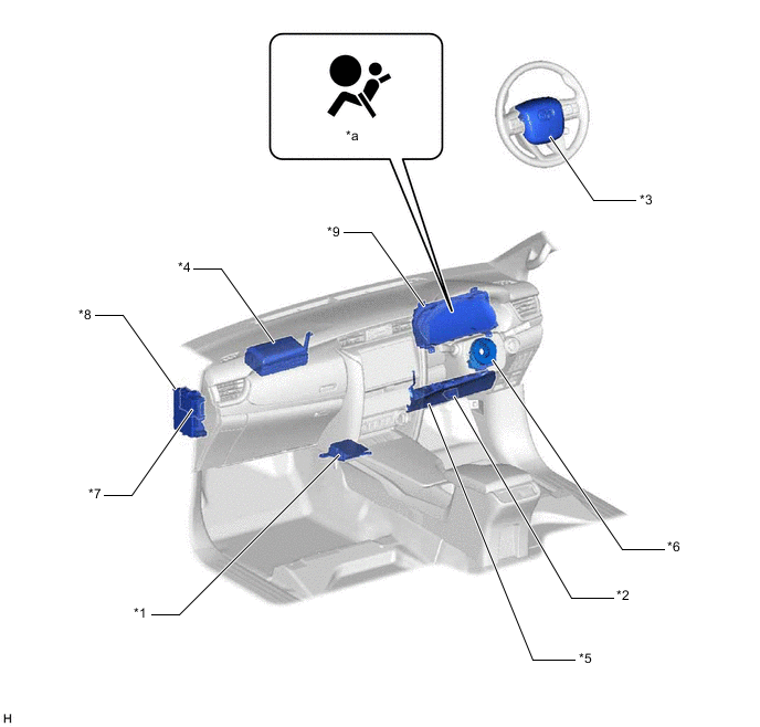
*1 AIRBAG SENSOR ASSEMBLY *2 DLC3 *3 INSTRUMENT PANEL PASSENGER AIRBAG ASSEMBLY *4 LOWER NO. 1 INSTRUMENT PANEL AIRBAG ASSEMBLY *5 SPIRAL WITH SENSOR CABLE SUB-ASSEMBLY *6 HORN BUTTON ASSEMBLY *7 BODY ECU *8 INSTRUMENT PANEL JUNCTION BLOCK ASSEMBLY
- A/BAG FUSE
*9 COMBINATION METER ASSEMBLY - - *a SRS WARNING LIGHT - -