FIT STANDARD / ADJUSTMENT METHOD ADJUSTMENT
-
INSPECT HOOD SUB-ASSEMBLY
-
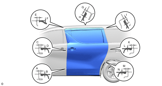
Check that the clearance measurements of areas A to F are within the standard ranges.
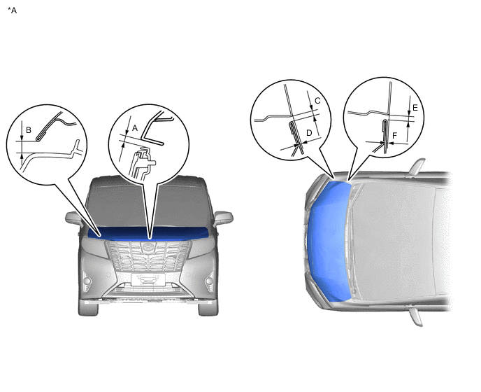
*A for ALPHRAD - - 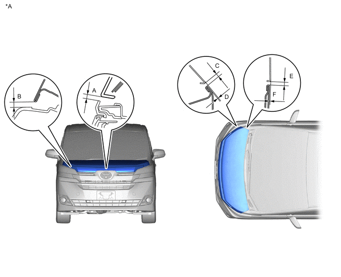
*A for VELLFIRE - -
Tech Tips
Centering bolts are used to mount the hood hinge to the vehicle body and door. The door cannot be adjusted with the centering bolts on. Substitute the centering bolts for standard bolts when making adjustments.
-
-
ADJUST HOOD SUB-ASSEMBLY
-
Adjust the hood position.
-
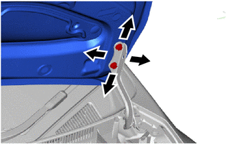
Loosen the 4 hinge bolts on the hood and adjust the hood position.
-
Move the hood and adjust the clearance between the hood and front fender.
-
Tighten the 4 hinge bolts on the hood after the adjustment.
- Torque:
- 11.5 N*m { 117 kgf*cm, 8 ft.*lbf }
-
-
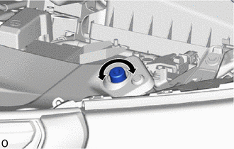
Adjust the cushion rubbers so that the hood and fender are aligned.
Tech Tips
Raise or lower the front end of the hood by turning the cushion rubber.
-
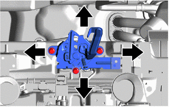
Adjust the hood lock.
-
Loosen the 3 bolts.
-
Adjust the hood lock position so that the striker can enter it smoothly.
-
Tighten the 3 bolts after the adjustment.
- Torque:
- 7.5 N*m { 76 kgf*cm, 66 in.*lbf }
-
-
-
INSPECT FRONT DOOR PANEL SUB-ASSEMBLY LH
-
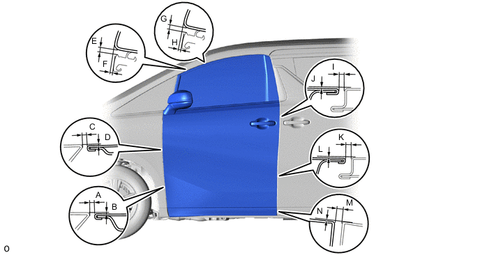
Check that the clearance measurements of areas A to N are within the standard ranges.
Tech Tips
-
Use the same procedure for the RH and LH sides.
-
The procedure listed below is for the LH side.
-
Centering bolts are used to mount the door hinge to the vehicle body and door. The door cannot be adjusted with the centering bolts on. Substitute the centering bolts for standard bolts when making adjustments.
-
-
ADJUST FRONT DOOR PANEL SUB-ASSEMBLY LH
-
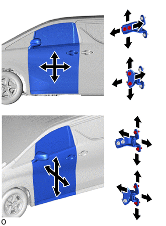
Using SST, loosen the hinge bolts on the body and adjust the door position.
- SST
- 09812-00010
-
Tighten the hinge bolts on the body after the adjustment.
- Torque:
- 26 N*m { 265 kgf*cm, 19 ft.*lbf }
-
Loosen the hinge bolts on the door and adjust the door position.
-
Tighten the hinge bolts on the door after the adjustment.
- Torque:
- 26 N*m { 265 kgf*cm, 19 ft.*lbf }
-
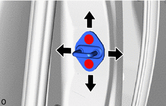
Using a T40 "TORX" socket wrench, adjust the striker position by slightly loosening the striker mounting screws and hitting the striker with a plastic-faced hammer.
-
Using a T40 "TORX" socket wrench, tighten the striker mounting screws after the adjustment.
- Torque:
- 23 N*m { 235 kgf*cm, 17 ft.*lbf }
-
-
INSPECT SLIDE DOOR SUB-ASSEMBLY LH
-
Check that the clearance measurements of areas A to N are within the standard ranges.
Tech Tips
-
Use the same procedure for the RH and LH sides.
-
The procedure listed below is for the LH side.
-
Centering bolts are used to mount the door hinge to the vehicle body and door. The door cannot be adjusted with the centering bolts on. Substitute the centering bolts for standard bolts when making adjustments.
-
-
ADJUST SLIDE DOOR SUB-ASSEMBLY LH
-
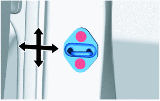
To adjust the door position vertically or horizontally at the slide door front lock striker plate assembly,loosen the bolts for the slide door down female stopper, loosen the striker screws using a T40 "TORX"socket wrench so that the striker can move, and then using a brass bar and hammer, adjust the strikerposition by tapping it lightly.
- Torque:
- 23 N*m { 235 kgf*cm, 17 ft.*lbf }
-
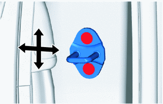
To adjust the door position vertically or horizontally at the slide door lock striker plate assembly, loosenthe striker screws using a T40 "TORX" socket wrench, and then using a brass bar and hammer, adjust theposition by tapping it lightly.
- Torque:
- 23 N*m { 235 kgf*cm, 17 ft.*lbf }
-
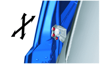
To adjust the door position in the vertical or front-to back directions at the rear edge of the door, loosen the bolts of the center slide door hinge assembly LH before making an adjustment.
- Torque:
- 19.5 N*m { 199 kgf*cm, 14 ft.*lbf }
-
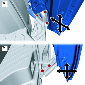
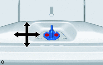
*a Door Side *b Vehicle Body Side To adjust the lower door seating position on the vehicle body surface vertically or to adjust the door position in the vertical and front-to-back directions, fully close the slide door, loosen the bolt of the lower slide door roller arm LH, and then check and adjust the door position.
- Torque:
- Door Side
- 19.5 N*m { 199 kgf*cm, 14 ft.*lbf }
- Vehicle Body Side
- 19 N*m { 194 kgf*cm, 14 ft.*lbf }
Tech Tips
To adjust the slide door lower roller base on the vehicle body side, disengage the slide door full open stop lock assembly and temporarily install the bolts.
-
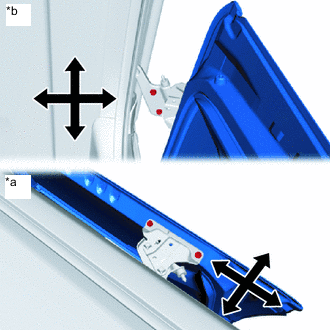
*a Door Side *b Vehicle Body Side To adjust the door position in the vertical, horizontal or front-to-back direction, loosen the bolts of the upper slide door roller assembly LH before making an adjustment.
- Torque:
- Door Side
- 11.5 N*m { 117 kgf*cm, 8 ft.*lbf }
- Vehicle Body Side
- 30 N*m { 306 kgf*cm, 22 ft.*lbf }
-
Temporarily tighten theslide door down female stopper, fully close the slide door to settle the stopper,and then fully tighten the stopper.
- Torque:
- 7.5 N*m { 76 kgf*cm, 66 in.*lbf }
-
After adjusting the door position, check the operation of the electricdoor lock system, slide door closer system, and power slide door system.
Tech Tips
If something contacts the power slide door touch sensor during an automaticclosing operation, the door will reverse.
-
-
INSPECT BACK DOOR PANEL SUB-ASSEMBLY
-
Check that the clearance measurements of areas A to N are within the standard ranges.
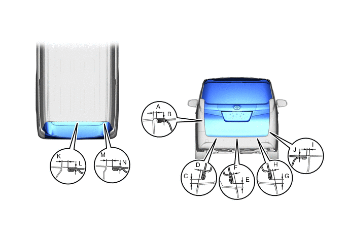
Tech Tips
Centering bolts are used to mount the door hinge to the vehicle body and door. The door cannot be adjusted with the centering bolts on. Substitute the centering bolts for standard bolts (with washers) when making adjustments.
-
-
ADJUST BACK DOOR PANEL SUB-ASSEMBLY
-
Before adjusting the upper end of the back door up and down or left and right, loosen the bolts.
-
Tighten the hinge bolts on the body after the adjustment.
- Torque:
- 19 N*m { 194 kgf*cm, 14 ft.*lbf }
-
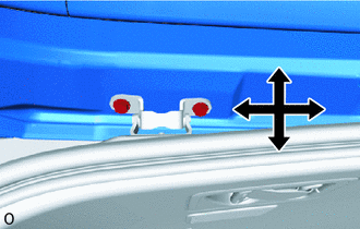
Using a T40 "TORX" socket wrench, adjust the striker position by slightly loosening the striker mounting screws and hitting the striker with a plastic-faced hammer.
-
Using a T40 "TORX" socket wrench, tighten the striker mounting screws after the adjustment.
- Torque:
- 23 N*m { 235 kgf*cm, 17 ft.*lbf }
-