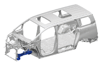
FRONT SIDE MEMBER CUT AND JOIN REPLACEMENT SECTIONS (LARGE AREAS)
-
With the front fender apron assembly removed.
-
REMOVAL
Symbol Meaning 
Remove Weld Points 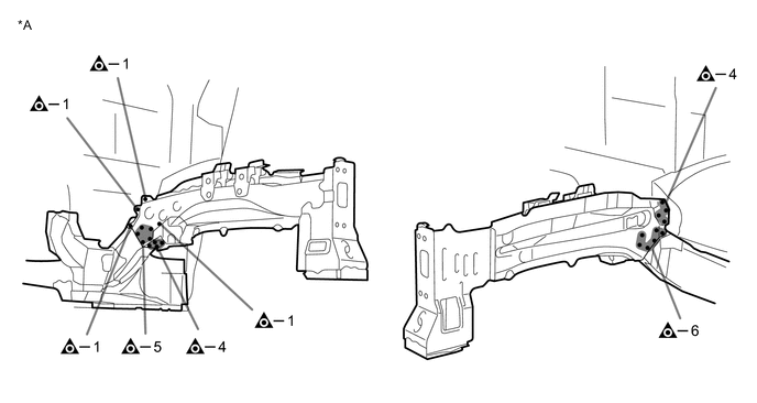
*A LH - - 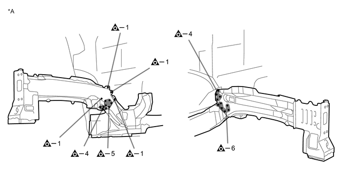
*A RH - - -
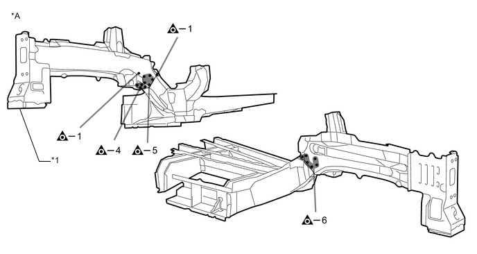
INSTALLATION
Symbol Meaning Remove Weld Points 
Plug Weld
-
Temporarily install the new parts and measure each part of the new parts in accordance with the body dimension diagram. (See the body dimensions)
-
Make sure to attach correctly in accordance with the body dimension diagram as this part affects the front wheel alignment.
-
If the entire supply part is not needed, remove the part of the supply part that is needed.
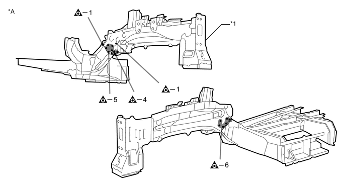
*A LH - - *1 FRONT SIDE MEMBER SUB-ASSEMBLY - - 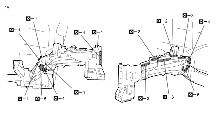
*A LH - - -
If the entire supply part is not needed, remove the part of the supply part that is needed.
*A RH - - *1 FRONT SIDE MEMBER SUB-ASSEMBLY - - 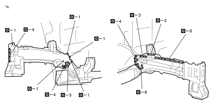
*A RH - - -
After welding, apply body sealer and undercoating to the corresponding parts. (See the painting/coating)
-
After applying the top coat, apply anti-rust agent to the internal panel portion of the closed section structural weld points.
-