FRONT SIDE MEMBER CUT AND JOIN REPLACEMENT SECTIONS (SMALL AREAS)
-
With the radiator support assembly removed.
-
REMOVAL
Symbol Meaning 
Remove Weld Points 
Remove Weld Points 
Cut and Join Location 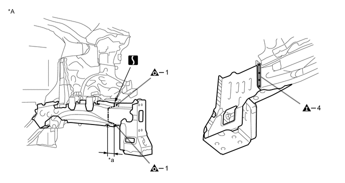
*A LH - - *a 40 mm (1.57 in.) - -
-
Carefully cut the front side member so not to damage A.
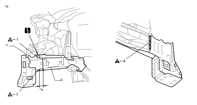
*A RH - - *1 FRONT SIDE MEMBER - - *a 40 mm (1.57 in.) - -
-
-
INSTALLATION
Symbol Meaning 
Plug Weld 
Plug Weld 
Butt Weld
-
Temporarily install the new parts and measure each part of the new parts in accordance with the body dimension diagram. (See the body dimensions)
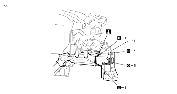
*A LH - - *1 FRONT SIDE MEMBER - - 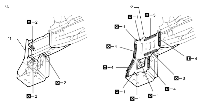
*A LH - - *1 FRONT SIDE MEMBER REINFORCEMENT SUB-ASSEMBLY NO.2 *2 FRONT SIDE MEMBER EXTENSION 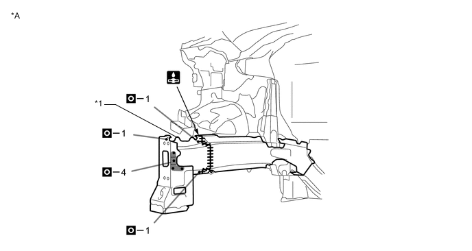
*A RH - - *1 FRONT SIDE MEMBER - - 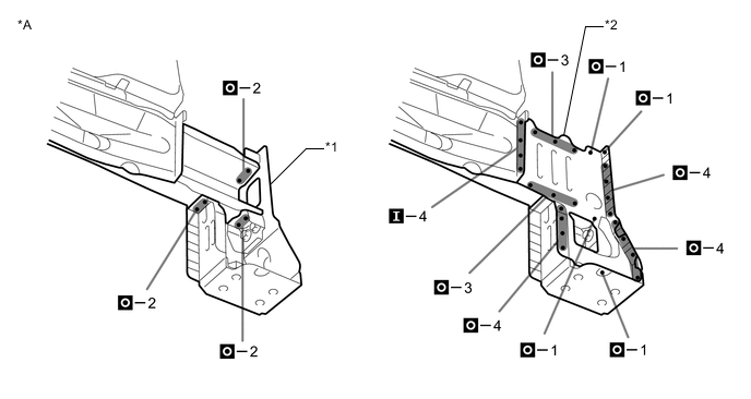
*A RH - - *1 FRONT SIDE MEMBER REINFORCE SUB-ASSEMBLY NO.2 *2 FRONT SIDE MEMBER EXTENSION -
After welding, apply body sealer to the corresponding parts. (See the painting/coating)
-
After applying the top coat, apply anti-rust agent to the internal panel portion of the closed section structural weld points.
-