FRONT FENDER FRONT APRON ASSEMBLY REPLACEMENT
-
With the radiator support assembly removed.
-
REMOVAL
Symbol Meaning 
Remove Weld Points 
Remove Weld Points 
Remove Weld Points
-
A indicates weld to remove for easier removal.
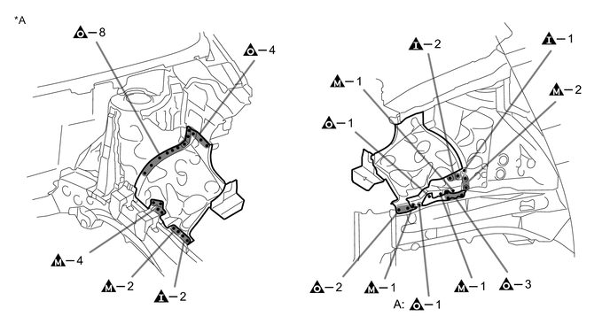
*A LH - - -
A indicates welds to remove for easier removal.
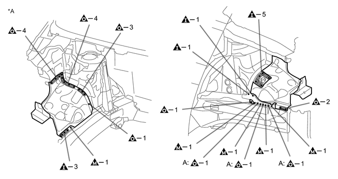
*A RH - -
-
-
INSTALLATION
Symbol Meaning 
Spot Weld 
Plug Weld 
Plug Weld 
Plug Weld
-
Inspect the fitting of the related parts around the new parts before welding. This affects the appearance of the finish.
-
Temporarily install the new parts and measure each part of the new parts in accordance with the body dimension diagram. (See the body dimensions)
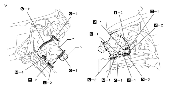
*A LH - - *1 FRONT FENDER APRON FRONT *2 RADIATOR SUPPORT TO FRONT FENDER BRACKET 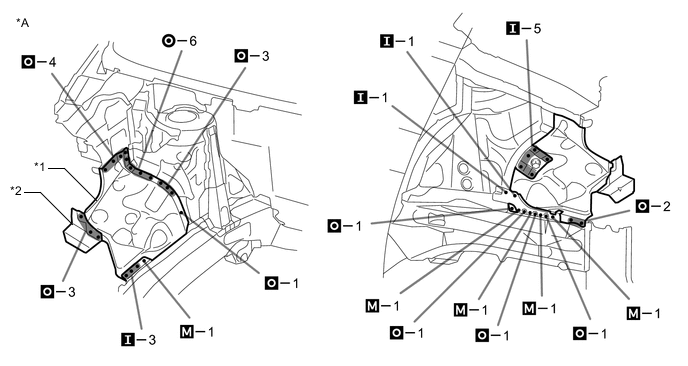
*A RH - - *1 FRONT FENDER APRON FRONT *2 RADIATOR SUPPORT TO FRONT FENDER BRACKET -
After welding, apply body sealer and undercoating to the corresponding parts. (See the painting/coating)
-
After applying the top coat, apply anti-rust agent to the internal panel portion of the closed section structural weld points.
-